
Coating solution for forming porous organic film

a technology of porous organic film and coating solution, which is applied in the direction of polyether coating, plastic/resin/waxes insulators, insulating bodies, etc., can solve the problems of not getting finer pore diameter due to foaming agent use, and the throughput is reduced, so as to achieve the effect of lowering the dielectric constan

Inactive Publication Date: 2003-03-18
SUMITOMO CHEM CO LTD
View PDF12 Cites 11 Cited by
  • Summary
  • Abstract
  • Description
  • Claims
  • Application Information

AI Technical Summary

Benefits of technology

The solution effectively reduces the dielectric constant of the porous organic film to 3.5 or less, enhancing insulation properties and preventing surface unevenness and stress, thus improving the film's durability and preventing wire breaking and dielectric constant deterioration.

Problems solved by technology

However, a silica film gets increased surface area, further have enhanced water absorption and tends to manifest deteriorated dielectric constant by a porous structure, since water absorption of the film itself is remarkable.
Consequently, surface hydrophobicizing treatment and the like are necessary, and throughput lowers.
A porous organic resin is already known as a construction material and insulation material, however, it can not get finer pore diameter due to use of a foaming agent.

Method used


Image

  • Coating solution for forming porous organic film
  • Coating solution for forming porous organic film
  • Coating solution for forming porous organic film

Examples


synthesis example

Synthesis of A)

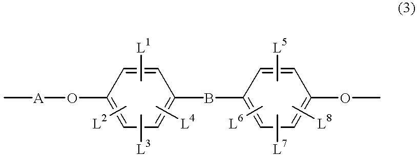
Into a 500 ml four-necked flask was charged 21.6 g (0.05 mol) of 1,1-bis(4-hydroxy-cyclohexypheyl)cyclohexylidene, 4.0 g of sodium hydroxide, 70.0 g of benzophenone and 50.0 g of toluene, and the mixture was dehydrated under reflux. After completion of the dehydration, 15.6 g (0.05 mol) of dibromobiphenyl was added. Further, a solution prepared by dissolving 0.05 g of cuprous chloride into 5 g of pyridine was added to this, and the mixture was allowed to react for 6 hours at an internal temperature of 185.degree. C. The mixture was cooled to room temperature, then, the reaction solution was added to a solution prepared by mixing 10 g of acetic acid with 600 g of methanol, to precipitate a product. The precipitated crystal was filtrated, washed with a large amount of methanol to obtain a polymer compound, and further, it was dried under reduced pressure for 8 hours at 60.degree. C.

To 4.0 g of thus obtained resin was added 100 ml of tetrahydrofuran, to dissolve the resi...

example 1

Resin A and Resin B obtained in the synthesis examples were dissolved in anisole, so as to give concentrations of 15% and 0.3%, respectively. Then, the solution was filtrated through a 0.2 .mu.m filter to prepared a coating solution.

The resulted coating solution was spin-coated on a 4 inch silicon wafer at a rotation of 2000 rpm, then, pre-baked for 1 minute at 150.degree. C. to remove most of anisole. Then, the product was subjected to heat treatment at 250.degree. C. (thermosetting initiation temperature) for 10 minutes, then, at 350.degree. C. for 30 minutes under nitrogen atmosphere.

The resulted porous film was cut together with the silicon wafer, and the resulted cross surface was vapor-deposited with palladium (deposited palladium film thickness: 1 nm), and the film thickness and pore diameter of cavity generated by the porous structure forming procedure were observed by watching with SEM (S-4700 type, manufactured by Hitachi, Ltd.). The film thickness was about 0.35 .mu.m, an...


PUM

PropertyMeasurementUnit
boiling pointaaaaaaaaaa
relative dielectric constantaaaaaaaaaa

Abstract

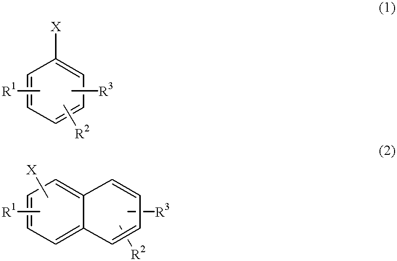
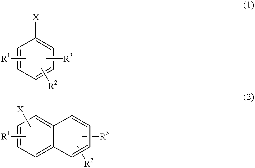
A coating solution for forming porous organic film comprising the following A) to C), wherein A) and B) have respective heat decomposition initiation temperatures Ta and Tb satisfying a relation: Ta>Tb:A) a thermosetting resin having an aromatic ring in the main chain,B) a heat decomposable resin obtained by polymerization of monomers which include at least one compound represented by the following formula (1) or (2), andC) an organic solvent,wherein, X and each of R1 to R3 are defined in the specification.

Description

1. Field of the InventionThe present invention relates to a porous organic film forming coating solution and a method for producing a porous organic film. Further, the present invention relates to a coating solution for forming a porous organic film suitable as an insulation film used in electronic devices, and a method for producing the porous organic film. More particularly, the present invention relates to a coating solution for forming a porous organic film suitable as an insulation film having low dielectric constant used in semiconductor parts, and a method for producing the porous organic film.2. Description of the Related ArtIn electronic parts, various insulation materials such as a layer insulation film, mold package material, wire coating material and the like are used. Recently, transferring speed of electron signals is respected for high speed communication, high speed processing and the like, and investigated from both of insulation material standpoint and wiring mater...

Claims


Application Information

Patent Timeline
Patent Type & Authority Patents(United States)
IPC IPC(8): B29C67/20C08L81/00C08L81/06C08L71/00C08L25/04C08L25/00C08G65/48C08F12/02C09D125/02C09D171/00C09D171/12C09D201/00H01B3/30H01B3/42H01B17/56
CPCB29C67/20C08L71/00C08L81/06C08L25/04C08L2666/04C09D171/12
Inventor YOSHIDA, YUJICHOI, HYUNCHEOLSUKUMODA, ATSUSHI
Owner SUMITOMO CHEM CO LTD
Learn More