
System and method employing indwelling RF catheter for systemic patient warming by application of dielectric heating

a dielectric heating and indwelling technology, applied in the field of patient warming systems, can solve the problems of generating higher body heat loss from convection and evaporation, surgical heat loss is further complicated, and the efficiency of a heat-blanket warming system is necessarily limited, and the rate of heat transfer is not easy to achiev

Inactive Publication Date: 2003-03-04
QUASIMOTO +1
View PDF83 Cites 124 Cited by
  • Summary
  • Abstract
  • Description
  • Claims
  • Application Information

AI Technical Summary

Benefits of technology

This method provides more effective warming by directly increasing the patient's core temperature, avoiding tissue damage and achieving higher power density than conventional methods, with the ability to systemically warm patients more efficiently.

Problems solved by technology

Second, anesthesia may have the effect of depressing the body's set-point temperature as regulated by the brain's thermal control center.
Third, in a surgical procedure, the patient may have his or her thoracic or abdominal cavities opened, greatly increasing the amount of surface area exposed to the atmosphere as compared to normal, and thereby generating higher body-heat losses from convection and evaporation.
Surgical heat loss is further complicated by the cool temperature of many surgical suites.
The rate of heat transfer, and therefore the effectiveness, of a heat-blanket warming system is necessarily limited for various reasons.
In addition to the problem of blood circulation to the extremities being reduced under conditions of hypothermia there are corollary issues to heating blanket methods, as well.
Another inherent limitation is the physical remoteness of the applied heat from the critical core location.
Because of the limitations of volume that can be infused into a patient during typical procedures, these devices lack the capacity to quickly rewarm patients with depressed body temperature.
Consequently, known patient warming approaches are not completely adequate for all applications due to certain unsolved problems.
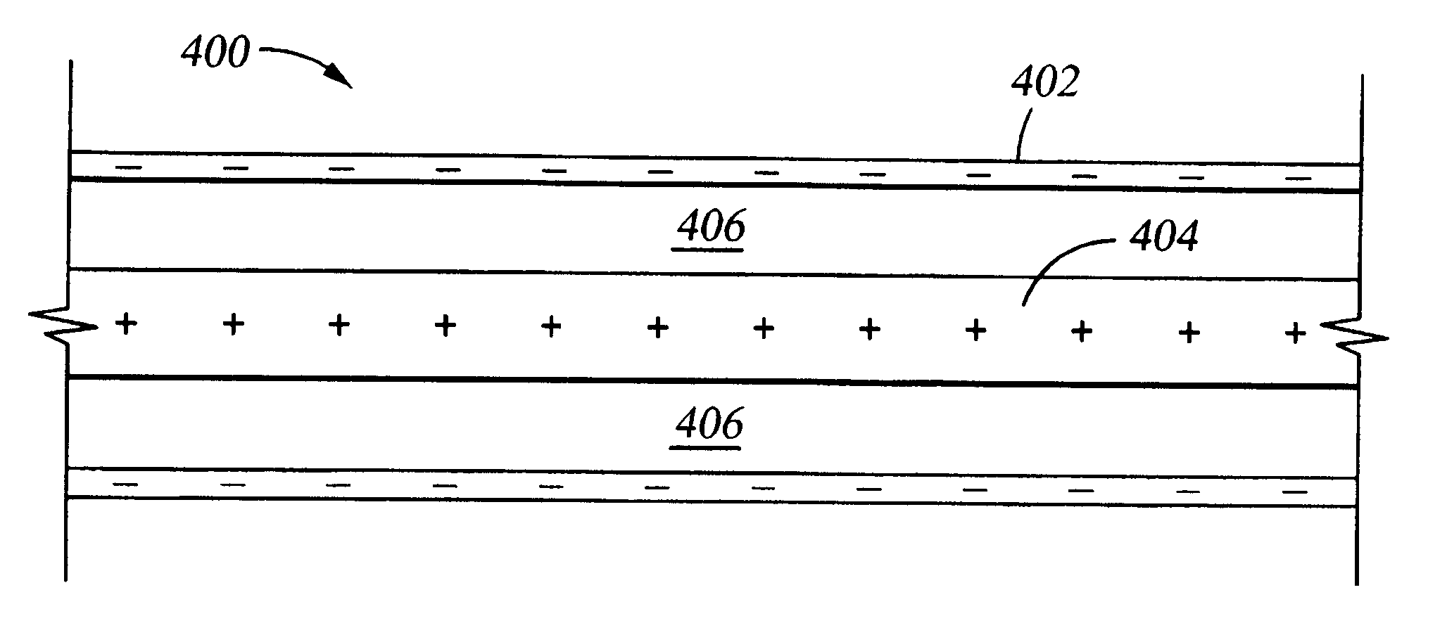
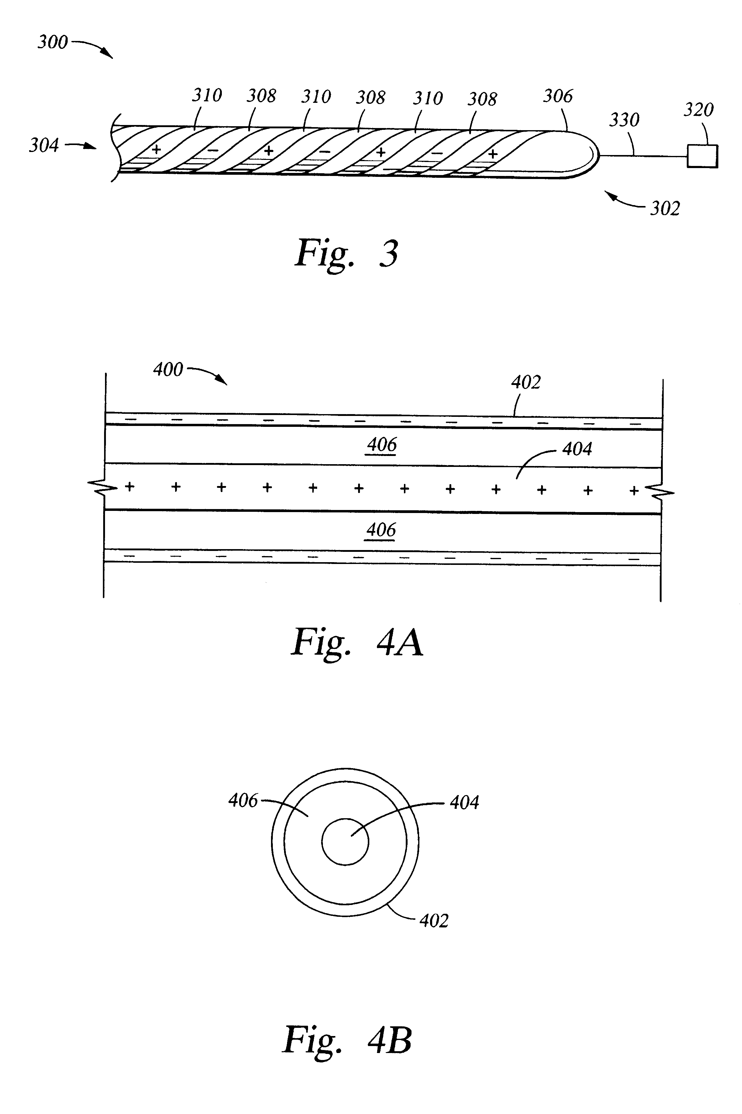
The emitter structure applies a controlled, high-frequency electric field to blood within the patient, thereby creating heat due to the dielectric loss properties of the blood, due in turn to its water content.
Thus, the effective heating power of the coaxial field design becomes progressively lower approaching the outer cylindrical electrode, helping to confine the heating effect to the flowing blood, and diminishing the threat of overheating adjacent fixed-position body structures.
For a strongly polar and high-dielectric-loss molecule, such as water, the inter-molecular "friction" of water molecules rubbing against one another as they try to follow the alternating field creates hysteresis losses and warms the bulk material.
This is similar to the method by which a microwave oven heats foods, and explains the common observation that a microwave oven is good at heating a cup of water to make tea, but bad at heating dry bread (which has low water content and low dielectric loss).
Only when there are dielectric losses in the material through which the field passes will power be absorbed from the electric field and result in heating.
Blood heating is therefore affected by the magnitude of RF field power and the time of exposure to this field.
The field's interaction with liquid blood in the blood vessel results principally from dielectric losses in the water component of the blood, creating distributed heating.
Furthermore, the catheter surface could not be heated much above 43.degree. C. as a means of increasing the heat transfer rate, as this approaches the protein denaturation temperature, at which irreversible damage will occur to the blood.

Method used


Image

  • System and method employing indwelling RF catheter for systemic patient warming by application of dielectric heating
  • System and method employing indwelling RF catheter for systemic patient warming by application of dielectric heating
  • System and method employing indwelling RF catheter for systemic patient warming by application of dielectric heating

Examples


Embodiment Construction

While the foregoing disclosure shows a number of illustrative embodiments of the invention, it will be apparent to those skilled in the art that various changes and modifications can be made herein without departing from the scope of the invention as defined by the appended claims. Furthermore, although elements of the invention may be described or claimed in the singular, the plural is contemplated unless limitation to the singular is explicitly stated. Additionally, ordinarily skilled artisans will recognize that operational sequences must be set forth in some specific order for the purpose of explanation and claiming, but the present invention contemplates various changes beyond such specific order.


PUM


Abstract

An indwelling RF catheter achieves warming of patients by dielectric heating of blood or other bodily fluids. In one example, the catheter is deployed in a suitable blood vessel, such as the inferior vena cava. The catheter design includes an emitter structure electrically coupled to an RF generator, which provides a source of RF power. The emitter structure, distally located upon the catheter, administers electromagnetic radiation to the blood within the patient, thereby creating heat due to the dielectric qualities of blood. As blood heated by the indwelling RF catheter courses through the patient's body, the patient's body is systemically warmed, raising the body core temperature.

Description

1. Field of the InventionThe present invention relates to patient warming systems to prevent and treat hypothermia, especially for surgical or other hospital patients.2. Description of the Related ArtIt is common for certain medical patients to experience mild to severe hypothermia. Some examples include trauma patients, people with a compromised circulatory system, and patients under anesthesia. There are several causes for this decrease of body temperature. First, anesthesia depresses the body's metabolic rate, meaning that the body burns calories at a reduced rate, and therefore generates less heat. Second, anesthesia may have the effect of depressing the body's set-point temperature as regulated by the brain's thermal control center. Third, in a surgical procedure, the patient may have his or her thoracic or abdominal cavities opened, greatly increasing the amount of surface area exposed to the atmosphere as compared to normal, and thereby generating higher body-heat losses from...

Claims


Application Information

Patent Timeline
Patent Type & Authority Patents(United States)
IPC IPC(8): A61F7/12A61M25/00A61B18/14A61B17/00
CPCA61M25/0017A61F7/12A61B18/1492A61B2017/00084A61F2007/126
Inventor WHITEBOOK, MARK EVANWALKER, BLAIR D.EVANS, SCOTT M.SHIMADA, LYNN M.
Owner QUASIMOTO
Learn More