
Dual mode adaptive threshold architecture for 3-D ladar FPA

a threshold architecture and ladar technology, applied in the field of imaging systems, can solve the problems of varying noise levels, unable to guarantee that every detector on the array is going to be exactly the same, and requiring more complex signal processing than current detector readout electronics can handl

Inactive Publication Date: 2003-02-18
RAYTHEON CO
View PDF6 Cites 67 Cited by
  • Summary
  • Abstract
  • Description
  • Claims
  • Application Information

AI Technical Summary

Problems solved by technology

One problem with flash ladar has to do with the need to compensate for variations in detector gain, noise, and atmospheric feedback.
There is no guarantee that every detector on the array is going to be exactly the same.
Some areas of the array may be more noisy than others, resulting in varying noise levels.
This problem is particularly prevalent with advanced detector arrays such as the APD (avalanche photo diode).
Handling bias adjustment internally in the detector signal processor requires more complex signal processing than current detector readout electronics can handle.
Readout electronics have been limited to simple signal processing due to the requirement of maintaining signal processing circuitry inside the unit cell.
The alternative is to have an individual control line to each cell, but this becomes a problem for large arrays.

Method used


Image

  • Dual mode adaptive threshold architecture for 3-D ladar FPA
  • Dual mode adaptive threshold architecture for 3-D ladar FPA
  • Dual mode adaptive threshold architecture for 3-D ladar FPA

Examples


Embodiment Construction

Illustrative embodiments and exemplary applications will now be described with reference to the accompanying drawings to disclose the advantageous teachings of the present invention.

While the present invention is described herein with reference to illustrative embodiments for particular applications, it should be understood that the invention is not limited thereto. Those having ordinary skill in the art and access to the teachings provided herein will recognize additional modifications, applications, and embodiments within the scope thereof and additional fields in which the present invention would be of significant utility.

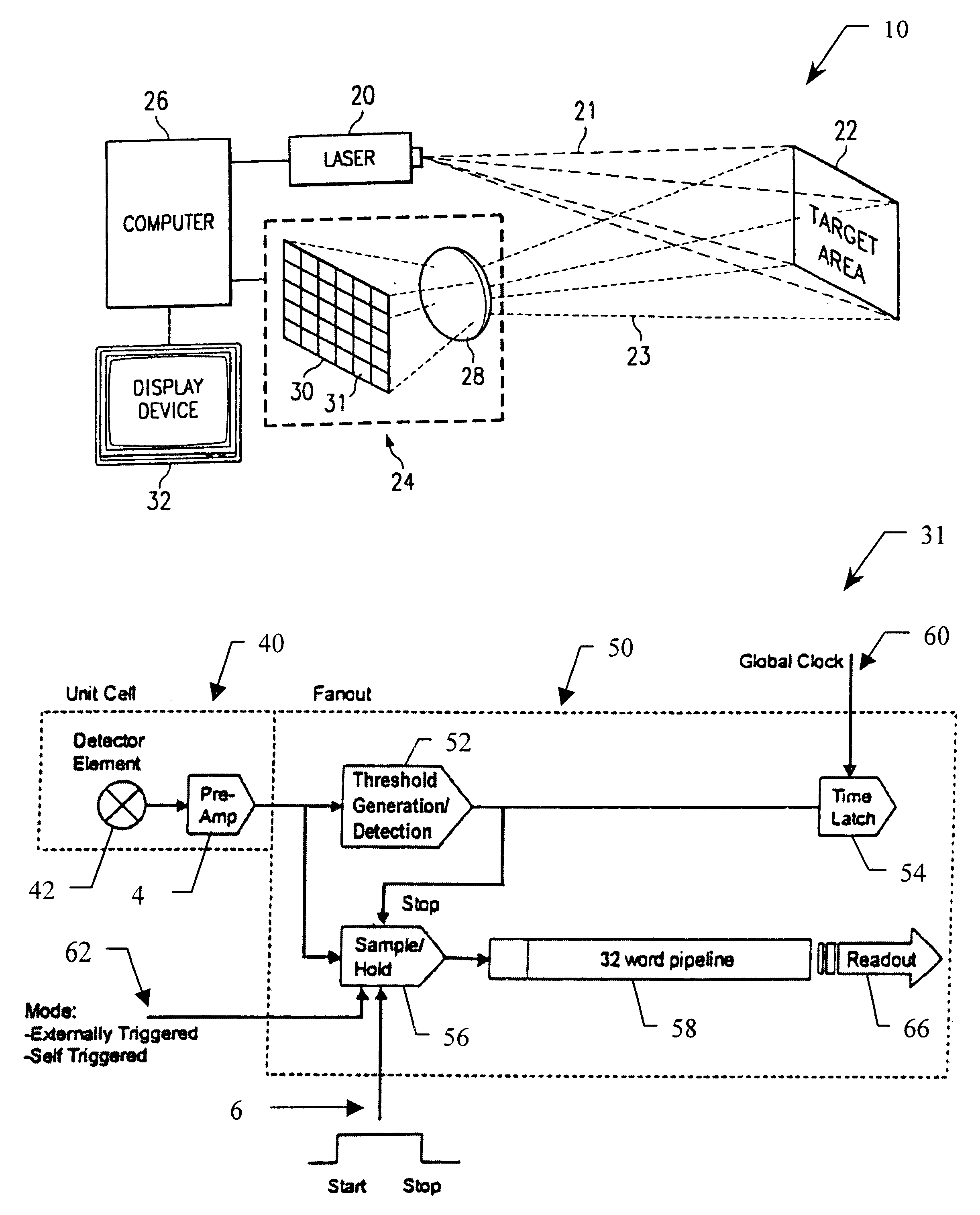
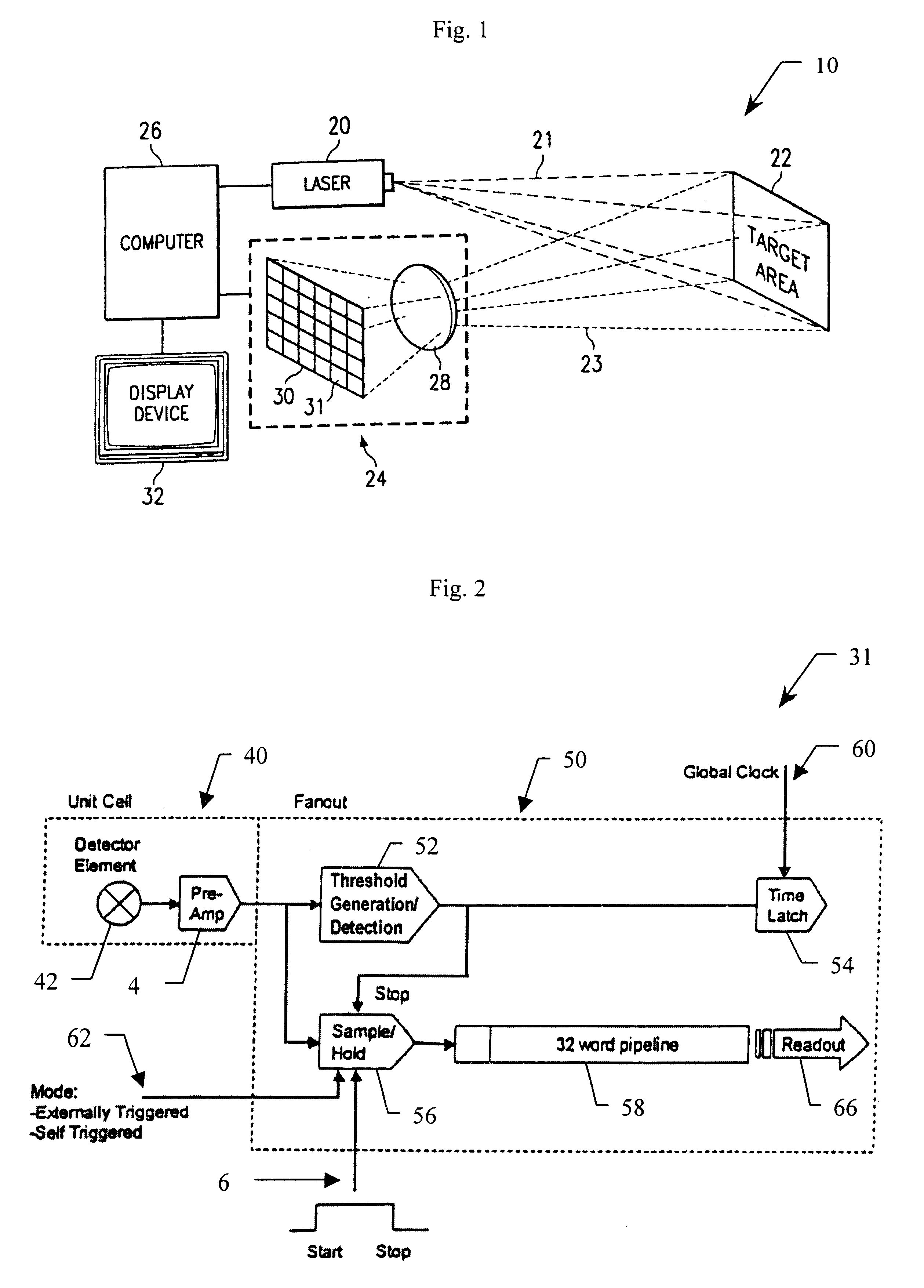
The present invention is an integrated signal processor for a detector in a focal plane array which internally compensates for variations in detector gain, noise, and aerosol backscatter. This invention is designed for use in a flash ladar system such as that described in U.S. patent application Ser. No. 09 / 330,953 entitled METHOD AND DEVICE FOR IDENTIFYING AN O...


PUM


Abstract

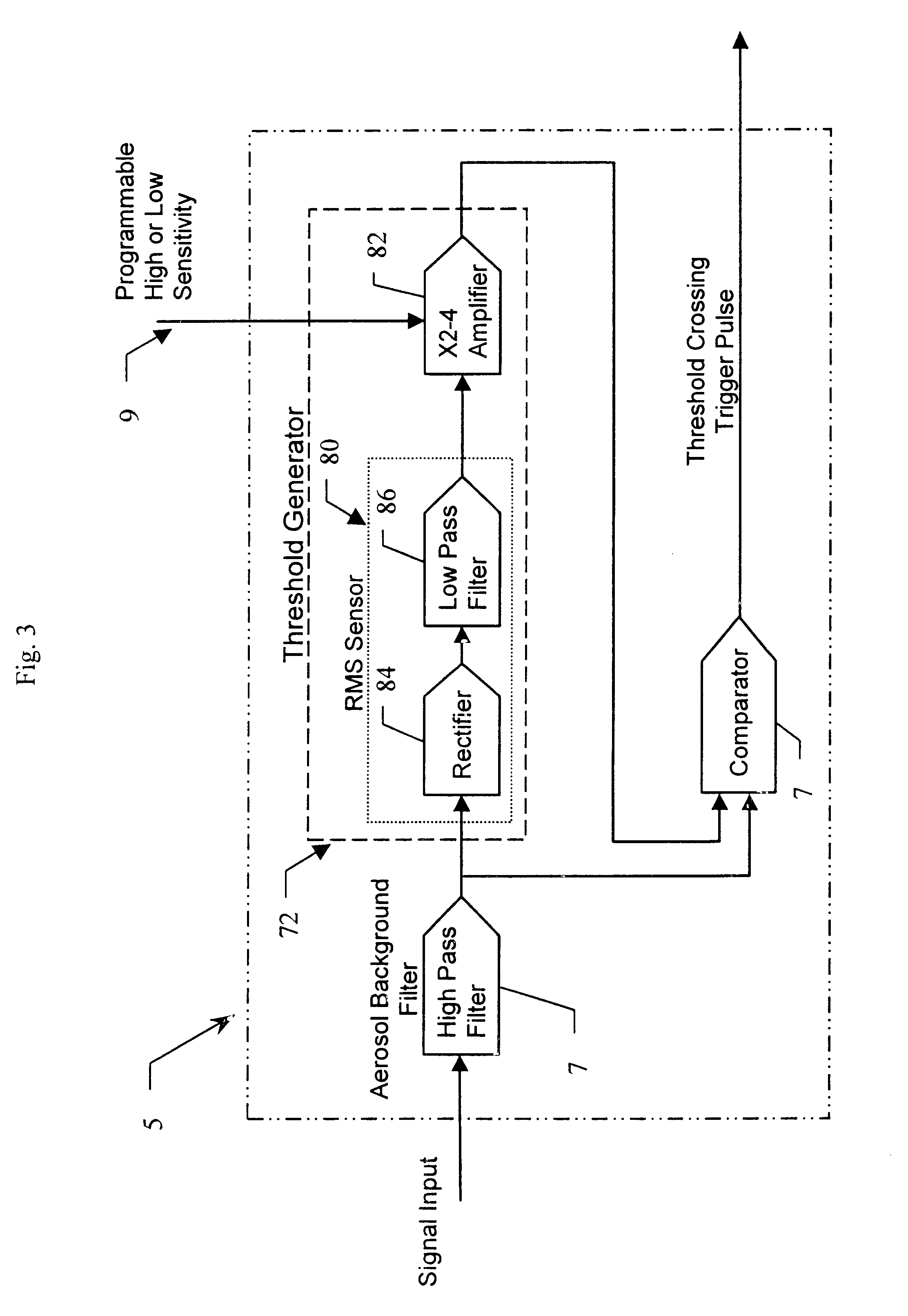
An integrated detector and signal processor (31) for ladar focal plane arrays (30) which internally compensates for variations in detector gain, noise, and aerosol backscatter. The invention (31) is comprised of a detector element (42) for receiving an input signal, a circuit (72) for generating a threshold based on the RMS noise level of the input signal, and a circuit (74) determining when the input signal is above that threshold. The detector element (42) is physically located in the interior of the detector array (30), while the signal processing circuitry (50) is located on the periphery of the array (30). In the preferred embodiment, the signal processor (31) also includes a circuit (56) for sampling the input signal and a circuit (58) storing multiple samples, allowing for multiple returns to be detected. In the preferred embodiment, the signal processor (31) can be operated in two modes: self triggered and externally triggered (range-gate mode). In the self triggered mode, the detector continually monitors and samples the incoming signal until a return is detected (by the thresholding circuit). In the range-gate mode, the detector stops sampling when it receives a signal from an external source. Once the data has been acquired, readout electronics (66) output the stored samples along with the stored "stopped" time code to an external computer (26).

Description

1. Field of the InventionThe present invention relates to imaging systems. More specifically, the present invention relates to threshold architecture for ladar systems.2. Description of the Related ArtA ladar (Laser Detecting and Ranging) system is an electro-optical system for object detection and ranging using a laser as an illuminator and a receiver which detects the return (reflection) of the laser from an object or target and converts the time of the return to range. This is done over two dimensions for a three dimensional range map. Up to now, most ladar systems have been of the scanning variety and are referred to as scanning ladar systems. In this type of ladar, a laser is pulsed at a high rate with one pulse per pixel (image element) or portion of the target area to be studied. The laser is scanned such that each pixel in the field of view is illuminated and detected. Each laser pulse may be reflected from the target area and received by a detector at the ladar site. The de...

Claims


Application Information

Patent Timeline
IPC IPC(8): G01S17/10G01S17/00G01S17/89G01S7/48G01S7/487G01S7/481G01S17/894
CPCG01S7/481G01S7/4873G01S17/89G01S17/10G01S17/894
Inventor HALMOS, MAURICE J.
Owner RAYTHEON CO
Learn More