
Fluid distribution system and process, and semiconductor fabrication facility utilizing same

a technology of distribution system and fluid, which is applied in the direction of water supply installation, container discharging method, separation process, etc., can solve the problems of difficult to achieve a reasonable high flow rate, and the inability of 3ms cylinders or other supply vessels containing liquefied compressed gas to be installed inside the semiconductor manufacturing facility (fab) in large quantity

Inactive Publication Date: 2002-09-24
ENTEGRIS INC
View PDF7 Cites 74 Cited by
  • Summary
  • Abstract
  • Description
  • Claims
  • Application Information

AI Technical Summary

Problems solved by technology

Due to its flammability, toxicity and its potential fluid release or spill, 3MS cylinders or other supply vessels containing the liquefied compressed gas cannot be installed inside the semiconductor manufacturing facility (fab) in large quantity.
Since the vapor pressure of the liquefied compressed gas is quite low at room temperature, and can be affected by the environmental temperature at the (outside the building) storage site, it is difficult to achieve a reasonably high flow rate (e.g., 6 standard liters per minute, slpm) in conventional flow lines during cold weather conditions.
In addition, condensation in the vapor delivery lines adversely affects the flow stability, and causes undesirable fluctuations in the desired line pressure and volumetric flow rate of the vapor deriving from the liquefied compressed gas.
Condensation in the tool can in some instances cause or require tool shutdown.
These are substantial problems that severely impact the use of liquefied compressed gases in the semiconductor manufacturing industry.
Corresponding problems attend the use of liquefied compressed gases in other industrial processes.

Method used


Image

  • Fluid distribution system and process, and semiconductor fabrication facility utilizing same
  • Fluid distribution system and process, and semiconductor fabrication facility utilizing same

Examples


Embodiment Construction

The disclosures of the following U.S. patents and patent applications are hereby incorporated herein by reference in their respective entireties: U.S. Pat. No. 5,518,528 issued May 21, 1996; U.S. Pat. No. 5,704,965 issued Jan. 6, 1998; U.S. Pat. No. 5,704,967 issued Jan. 6, 1998; U.S. Pat. No. 5,707,424 issued Jan. 13, 1998; U.S. patent application No. 09 / 300,994 filed Apr. 28, 1999 in the names of Luping Wang and Glenn M. Tom for "FLUID STORAGE AND GAS DISPENSING SYSTEM;" U.S. patent application No. 09 / 067,393 filed Apr. 28, 1998 in the names of Luping Wang and Glenn M. Tom for "FLUID STORAGE AND GAS DISPENSING SYSTEM;" and U.S. patent application No. 09 / 532,268 filed Mar. 22, 2000 in the name of Luping Wang for "COMPRESSED FLUID DISTRIBUTION SYSTEM AND METHOD, AND SEMICONDUCTOR FABRICATION FACILITY UTILIZING SAME."

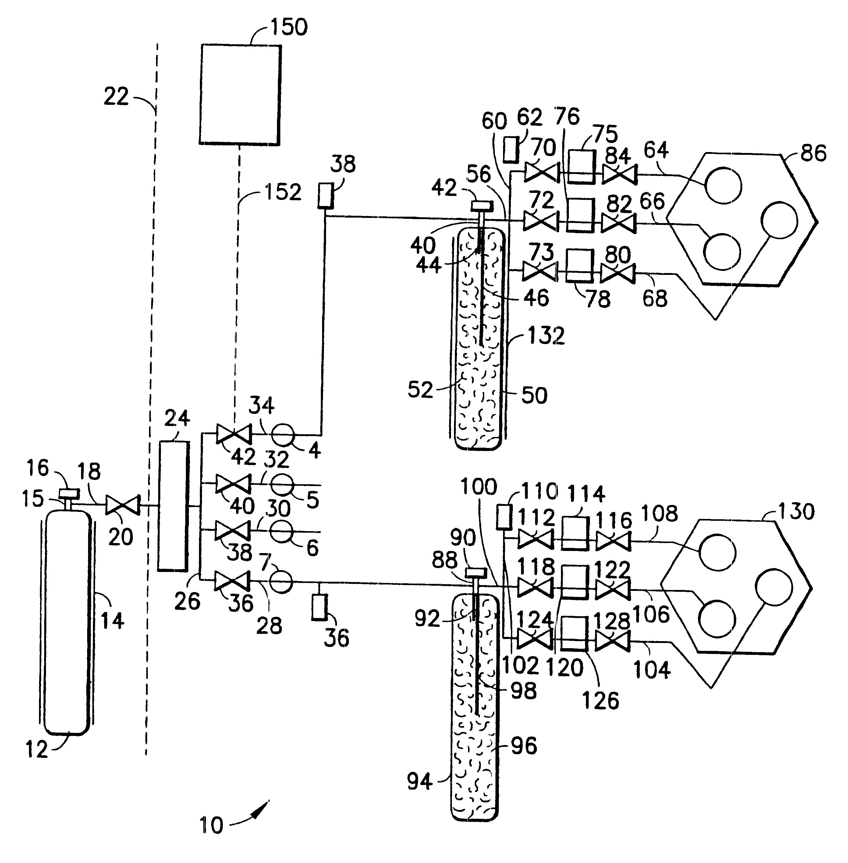
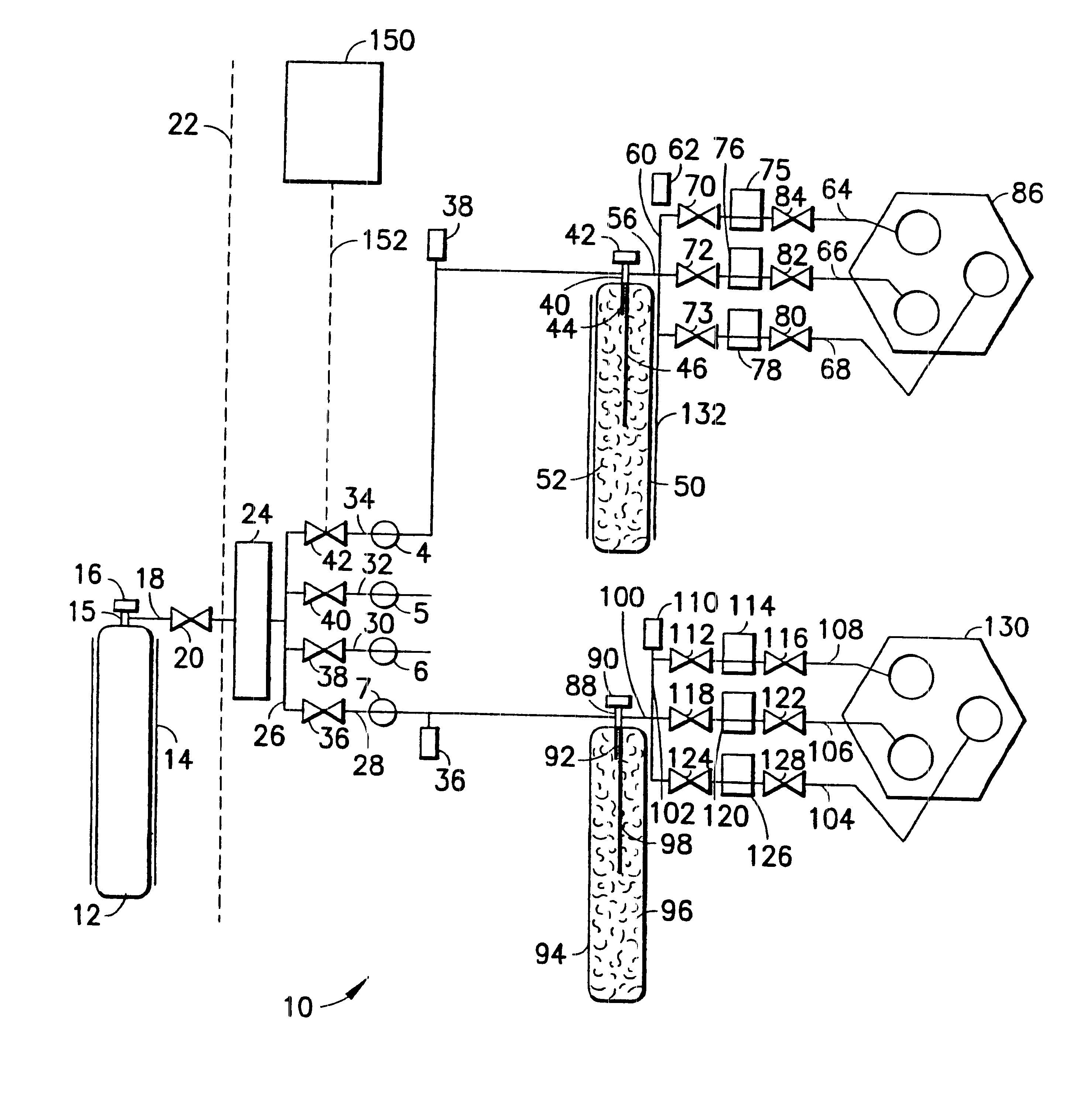
The fluid distribution system and process of the present invention provide a means and method for supplying a fluid from a source of same to a local supply vessel. The i...


PUM


Abstract

A fluid distribution system for supplying a gas to a process facility such as a semiconductor manufacturing plant. The system includes a main fluid supply vessel coupled by flow circuitry to a local sorbent-containing supply vessel from which fluid, e.g., low pressure compressed gas, is dispensed to a fluid-consuming unit, e.g., a semiconductor manufacturing tool. A fluid pressure regulator is disposed in the flow circuitry or the main liquid supply vessel and ensures that the gas flowed to the fluid-consuming unit is at desired pressure. The system and associated method are particularly suited to the supply and utilization of liquefied compressed gases such as trimethylsilane, arsine, phosphine, and dichlorosilane.

Description

This invention relates to a fluid distribution system and process, useful in applications such as manufacturing semiconductor materials and devices.DESCRIPTION OF THE RELATED ARTIn the semiconductor manufacturing field, trimethylsilane (3MS) and other liquefied compressed gases such as dichlorosilane, arsine and phosphine have been widely used or are currently emerging as important precursors for low dielectric constant (low k) materials in the fabrication of capacitors, memory cells and other microelectronic device structures.As used herein, the term "low pressure" refers to pressure levels below about 1500 torr, the term "liquefied compressed gases" refers to fluids that are in liquid form at 25.degree. C. and the term "low pressure compressed liquefied gas" refers to fluids that are in liquid form at 25.degree. C. at pressure <100 psig.The challenge attending the use of these liquefied compressed gas materials is to provide safe and efficient storage and delivery to the tools ...

Claims


Application Information

Patent Timeline
IPC IPC(8): F17C13/04F17D1/00F17C11/00F17D1/04
CPCF17C11/00F17C13/04F17D1/04F17C2265/01F17C2270/0518F17C2205/0146F17C2205/0323F17C2205/0338F17C2221/05F17C2223/0153F17C2223/033F17C2250/032F17C2250/0626F17C2250/0636Y10T137/0318Y10T137/4807Y10T137/6416Y10T137/86187
Inventor WANG, LUPINGTABLER, TERRY A.DIETZ, JAMES A.
Owner ENTEGRIS INC
Learn More