Eureka AIR delivers breakthrough ideas for toughest innovation challenges, trusted by R&D personnel around the world.

Tool for chip removing machining and methods and apparatus for making the tool

a technology of machining and tools, applied in the direction of turning apparatus, baking, dough shaping, etc., can solve the problems of bringing about a plurality of drawbacks, dust, and the formation of green bodies (pressed but not sintered materials) will not endure handling to any degree, so as to eliminate the drawbacks of the known technique

Inactive Publication Date: 2002-09-17
SECO TOOLS AB
View PDF19 Cites 62 Cited by
  • Summary
  • Abstract
  • Description
  • Claims
  • Application Information

AI Technical Summary

Benefits of technology

One object of the present invention is to provide a method and a device, whereby the drawbacks of the known technique are eliminated.

Problems solved by technology

That known technique brings about a plurality of drawbacks during manufacture of elongated slender bodies.
The powder gives off dust, and the formed green body (pressed but not sintered material) will not endure handling to any degree.
Furthermore the chip flutes must be formed by grinding which is time consuming.
The method of injection molding brings about a high degree of freedom concerning geometry but brings about troubles during manufacture of elongated slender bodies and costly investments in molds.
A drawback of the known technique is that the useful life of the tool is less than desired.

Method used


Image

  • Tool for chip removing machining and methods and apparatus for making the tool
  • Tool for chip removing machining and methods and apparatus for making the tool
  • Tool for chip removing machining and methods and apparatus for making the tool

Examples


Embodiment Construction

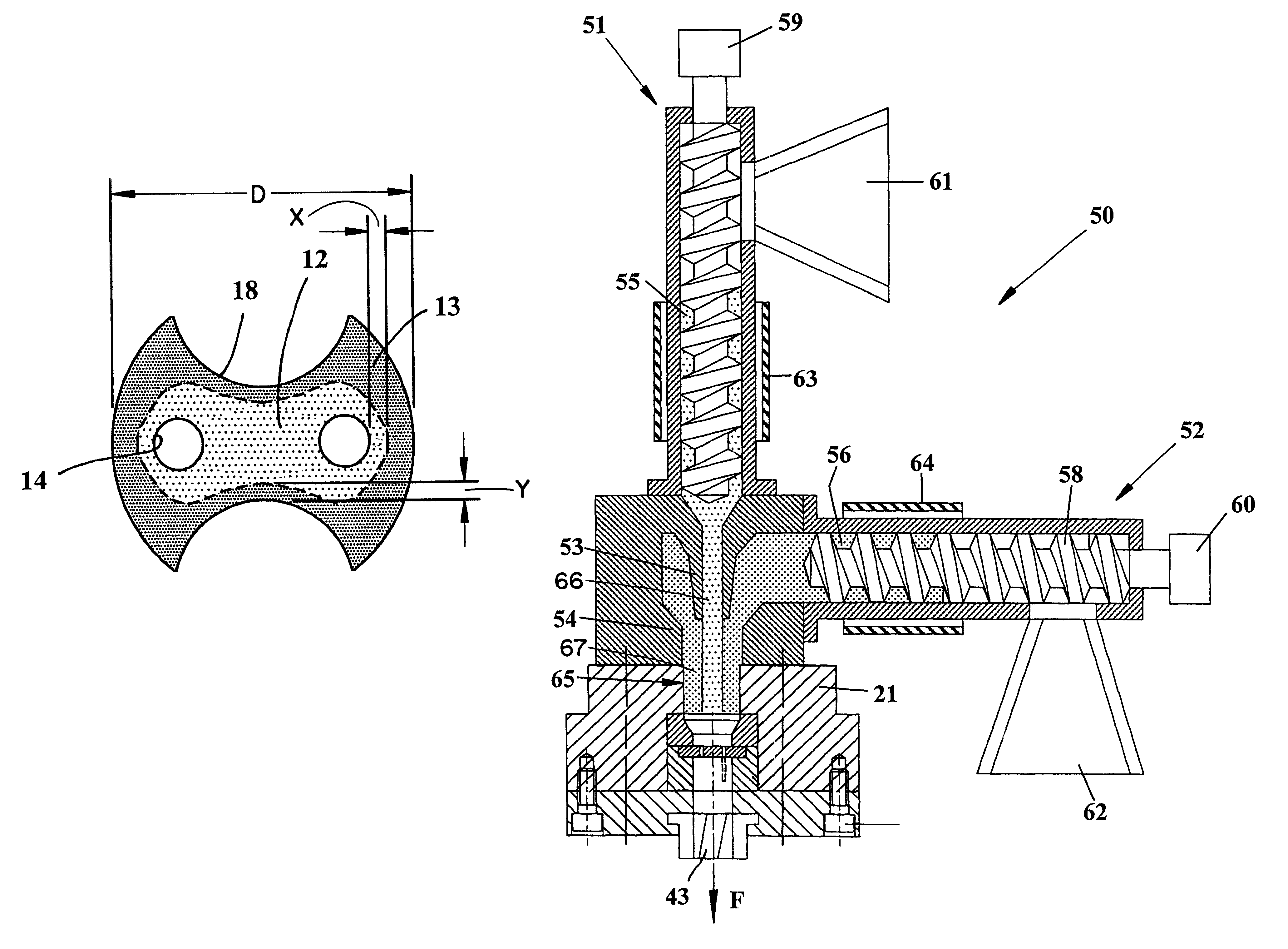
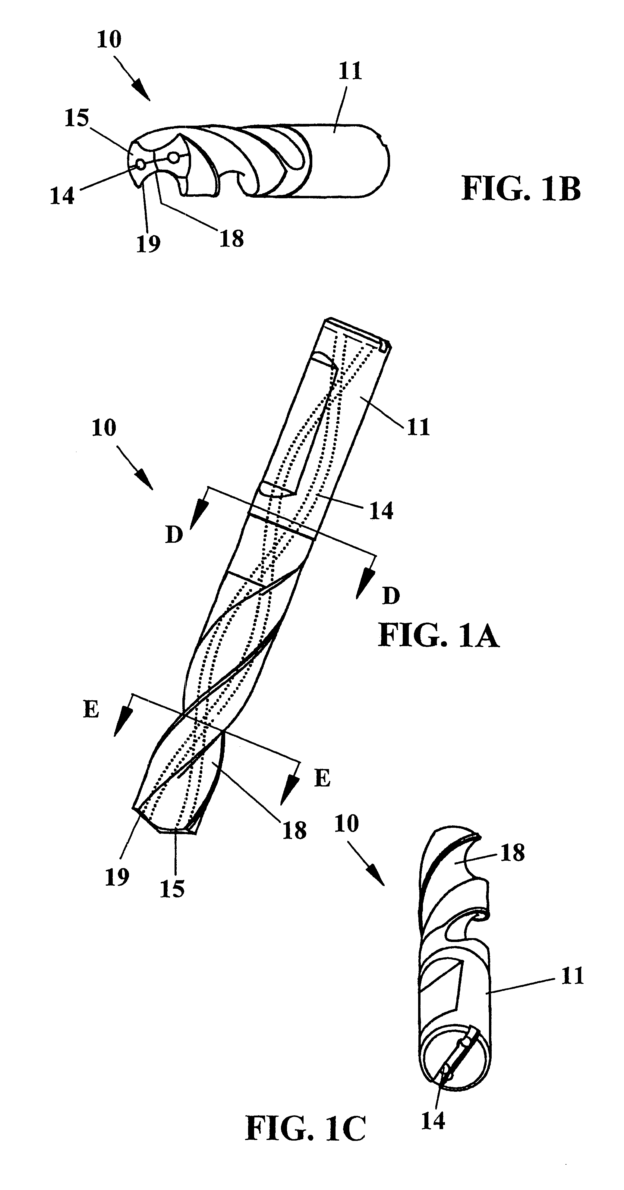
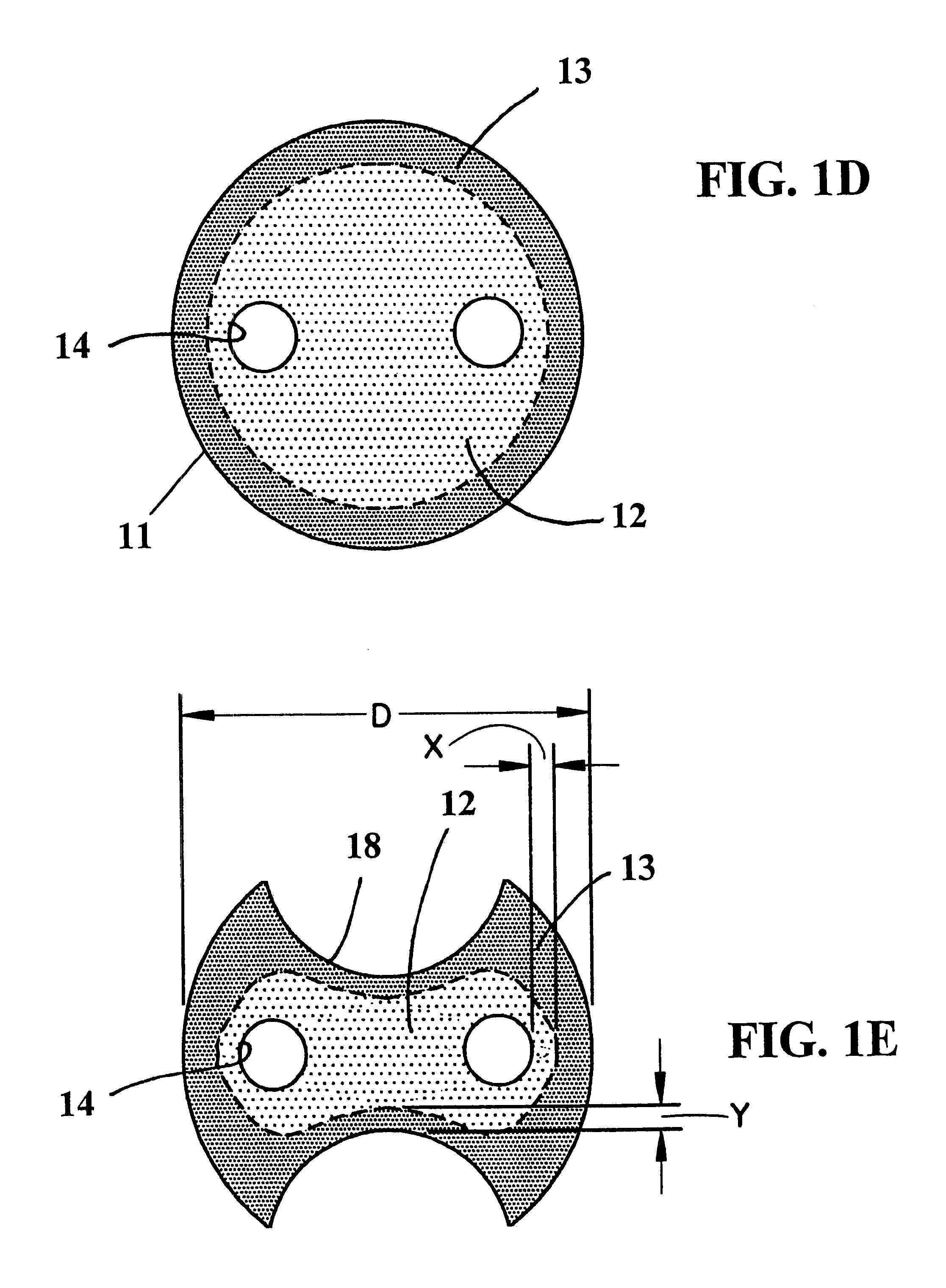
The embodiment of a tool shown in FIGS. 1A-1C is a so-called helix drill. The drill 10 comprises a substantially solid shank 11 having a first tip forming end comprising at least one cutting edge 19, and a number of chip flutes 18 that are equal in number to the cutting edges. The drill comprises a central core portion of relatively tough hard material connected to an outer peripheral tube portion 13 of relatively wear resistant hard material. The drill 10 is made of solid hard material, such as extruded hard metal, and the helical chip flutes 18 can extend along the entire body or along a part thereof. The shank 11 shall be secured into a rotatable spindle, not shown. The drill has two upper clearance surfaces 15.

The drill is extruded from two different materials where the difference between the materials lies in the relative ratio of hard substance (for example wolfram carbide, WC) to binder (for example cobalt, Co). That is, the central portion has a larger binder ratio than the ...


PUM

PropertyMeasurementUnit
Electrical resistanceaaaaaaaaaa
Ratioaaaaaaaaaa
Shapeaaaaaaaaaa

Abstract

A tool for chip-forming machining is made by passing first and second compounds through first and second coaxial dies, respectively, whereby the first material forms a center core of the tool, and the second material forms an outer rod of the material. The material of the core is tougher and less wear-resistant than the material of the outer rod. The coaxial first and second compounds are passed through a shaping die and then through a flute-forming structure which forms chip flutes in the outer rod.

Description

The present invention relates to a tool for chip removing machining comprising a relatively tough core connected to a relatively wear resistant outer periphery, and to methods and apparatus for making the tool.It is previously known through for example WO 98 / 28455 to press a core and a surrounding tube of material powder in two steps. The material powder comprises wolfram carbide (WC), also known as tungsten carbide, together a with cobalt (Co) binder that are compressed between a punch and a die, and that subsequently are sintered such that the binder metal is melted and binds the carbide to form a tool material for chip removing machining. Thus, there results a tube formed around, and connected to, an inner core. The core has a higher binder (cobalt) ratio than does the tube, whereby the core is tougher than the tube, but the tube is harder and more wear resistant than the core.That known technique brings about a plurality of drawbacks during manufacture of elongated slender bodie...

Claims


Application Information

Patent Timeline
IPC IPC(8): B21C23/02B21C23/14B22F7/06B22F3/20B23B51/06B23P15/32B23B51/00B21C23/10B22F3/02B22F3/22B22F5/10B22F7/00
CPCB21C23/147B22F3/20B22F3/227B22F7/06B23B51/06B23P15/32B22F2005/001Y10T408/455B22F2998/00Y10T408/78B21C23/10
Inventor PUIDE, MATTIASBRUHN, JOHNNYGRONKVIST, MIKAEL
Owner SECO TOOLS AB
Why Eureka
Eureka Blog
Learn More