
Melt-blown non-woven fabric, and nozzle piece for producing the same

a technology for nozzles and non-woven fabrics, which is applied in the direction of melt spinning methods, weaving, filament/thread forming, etc., and can solve the problems of increased production cost, increased service life, and difficult processing control

Inactive Publication Date: 2001-11-20
TONEN TAPYRUS
View PDF7 Cites 122 Cited by
  • Summary
  • Abstract
  • Description
  • Claims
  • Application Information

AI Technical Summary

Benefits of technology

The melt-blown non-woven fabric produced using the nozzle piece of the present invention is composed of fibers produced in one step by melt blowing to have a varying diameter in a range from 1 to 10 .mu.m and adequately dispersed to form a mono layer fabric. The nozzle piece of the present invention gives a non-woven fabric of wide fiber diameter distribution and efficiently produces a filter media exhibiting filtration characteristics comparable to those of the conventional non-woven fabric material, in which two or more fabrics with different fiber diameter, produced separately, are laminated with each other.

Problems solved by technology

However, a filter composed of very fine fibers tends to be clogged in a short time with the particles and such clogging decreases service life, although it can capture very fine particles.
These methods, however, tend to increase production cost, and also require delicate processing control.
Such additional process may cause quality-related problems, e.g., deterioration of the fabrics by heat or delamination during the service period.
R above 2.0 is also undesirable, because an unbalanced discharge of molten polymer occurs, then many shots originate.
Db below 0.20 mm is undesirable, because of difficulty in machining of such a nozzle.

Method used


Image

  • Melt-blown non-woven fabric, and nozzle piece for producing the same
  • Melt-blown non-woven fabric, and nozzle piece for producing the same

Examples


example 1

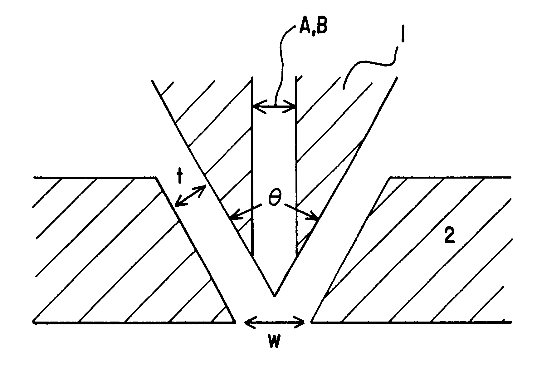
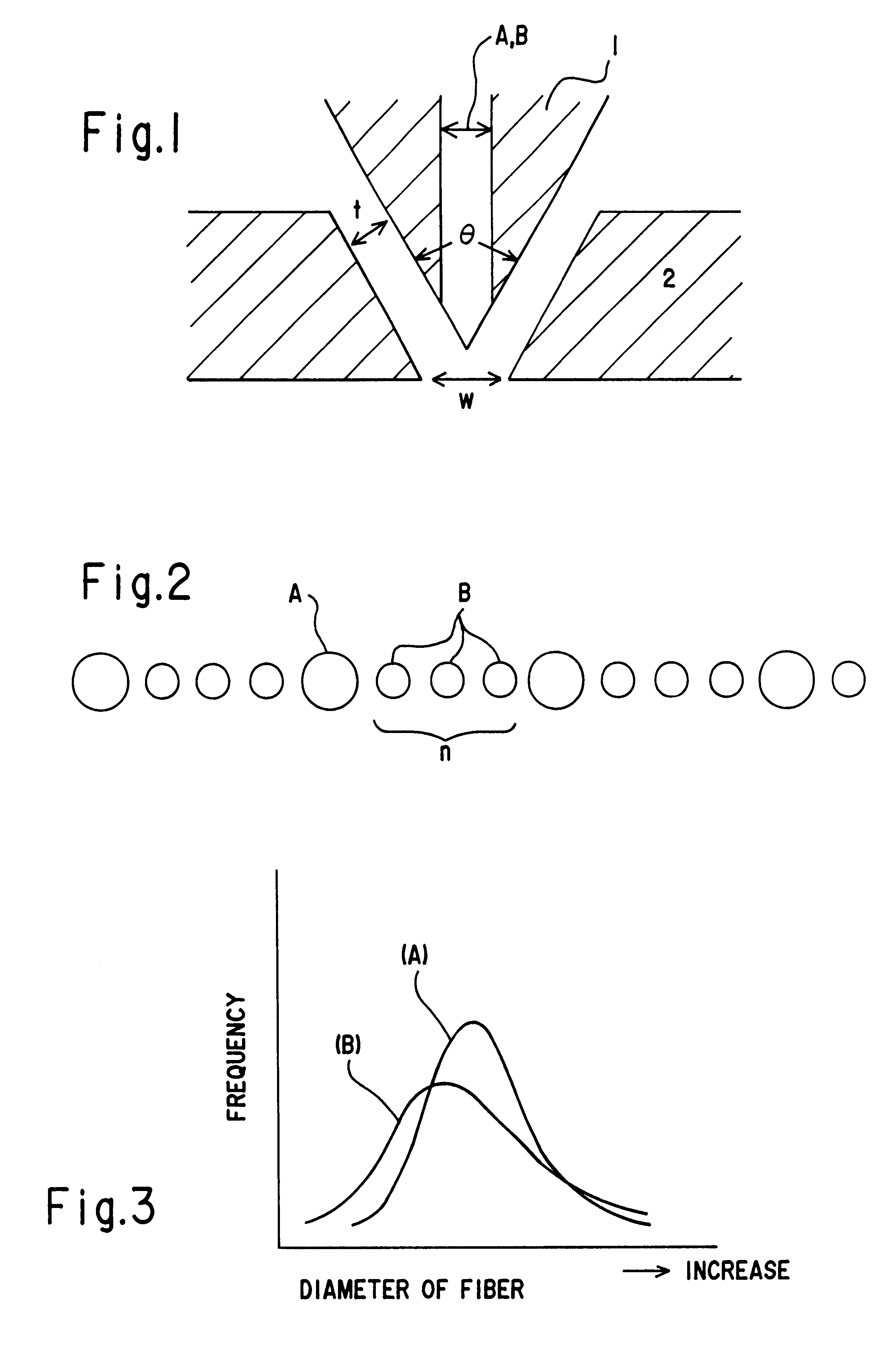
The same procedure as used for COMPARATIVE EXAMPLE 1 was repeated, except that the nozzle piece was replaced by the one equipped with nozzles A (hole diameter Da: 0.6 mm) and nozzles B (hole diameter Db; 0.4 mm), 2 of which were disposed between the two adjacent nozzles A, to form a non-woven fabric having an average fiber diameter of 5.6 .mu.m.

Its fiber diameter and fiber diameter distribution were determined by the same procedures as used for COMPARATIVE EXAMPLE 1. Its fiber diameter distribution was compared with that of the fabric prepared by COMPARATIVE EXAMPLE 1, to judge the difference. The number of shots and also filtration efficiency of the non-woven fabric were measured In the same procedures as used for COMPARATIVE EXAMPLE 1. The results are given in Table 1.

examples 2 to 3

, and Comparative Examples 2 to 5

The procedure as used for COMPARATIVE EXAMPLE 1 was applied for making each of these EXAMPLES and COMPARATIVE EXAMPLES, as shown in Table 1, the nozzle piece was replaced by the one equipped with nozzles A (hole diameter: Da) and nozzles B (hole diameter: Db) of varying hole diameter ratio R (Da / Db) and number (n) of the nozzles B between the adjacent nozzles A, to form a non-woven fabric.

[Table 1]

As shown in Table 1, the nozzle piece of the present invention which is equipped with 2 or 4 smaller nozzles B set between adjacent larger nozzles A(EXAMPLES 1 to 3) gives a non-woven fabric of wider fiber diameter distribution and longer service life than the one which is equipped with nozzles of the same hole diameter (prepared by COMPARATIVE EXAMPLE 1). In case when nozzle diameter ratio R is set at 1.2, which is below the range of the present invention, the non-woven fabric has a narrower fiber diameter distribution and hence shorter service life, altho...


PUM

PropertyMeasurementUnit
hole diameteraaaaaaaaaa
Da/Dbaaaaaaaaaa
Da/Dbaaaaaaaaaa

Abstract

The nozzle piece of the present invention is provided with circular cross sectional nozzles having different sizes disposed in a row in front of the die, with n-numbered smaller nozzles B (hole diameter: Db) between adjacent larger nozzles A (hole diameter: Da). It gives melt-blown non-woven fabric of monolithic structure in one step, composed of fine fibers having a diameter in a range from 1 to 10 mum diameter Variance ratio F of 2.0 or more and wide fiber diameter distribution.

Description

1. Field of the InventionThis invention relates to a melt-blown non-woven fabric having a wide fiber diameter distribution, in which fine fibers with different diameters are adequately dispersed, and also to a nozzle piece applied for producing the same.2. Prior ArtProduction of non-woven fabrics by melt blowing has been known since a long time. The principle was disclosed by, e.g., U.S. Naval Research Laboratory's Report No. 5256, Feb. 11, 1959. It was also described in detail by EXXON Chemical, which commercialized the production for the first time in the world, in Japanese Laid-open Patent Application No. 50-46972 and "Melt Blowing-One-step Web Process for New Non-woven Products (Tappi Journal, vol. 56, No.4, April, 1973).In this process, a number of nozzles of a given diameter is disposed at a given "hole-to-hole" pitch in front of the die, and molten polymer discharged therefrom is spun in a flow of a hot air jet, wherein a non-woven fabric is produced with fine fibers having a...

Claims


Application Information

Patent Timeline
Patent Type & Authority Patents(United States)
IPC IPC(8): D04H3/08D04H3/10D04H1/46D01D5/098D04H1/56D04H3/16
CPCD01D5/0985D04H1/565D04H3/16D04H1/56Y10T442/615Y10T442/614Y10T442/689Y10T442/68Y10T442/626Y10T442/621Y10T442/682D04H3/016
Inventor MIKAMI, TAKASHI
Owner TONEN TAPYRUS
Learn More