
Method for forming a metallic coat by impacting metallic particles on a workpiece

a technology of metallic particles and workpieces, applied in the direction of solid-state diffusion coatings, coatings, printed circuit manufacture, etc., can solve the problems of high cost, long time, and high adhesion of coats and etchings

Inactive Publication Date: 2001-09-18
FUJI KIHAN CO LTD
View PDF21 Cites 24 Cited by
  • Summary
  • Abstract
  • Description
  • Claims
  • Application Information

AI Technical Summary

Benefits of technology

Another object of the present invention is to provide a metallic coat forming method particularly for prevention of nitriding. In this method, the metallic coat, which has high density as well as high strength of adhesion to the surface of work material and which can be easily peeled from the surface of work material after nitriding, is formed on the surface of work material at its part where the nitriding should be prevented, so that the nitrogen can be surely prevented from dispersing in the part on which the metallic coat has been formed, during the nitriding of work material.

Problems solved by technology

In the above conventional methods, by the method where the metallic coat is formed by merely painting, adhesion is too low.
Further, by the other conventional method where the metallic coat formed by electroplating or the like is subjected to etching, several kinds of chemicals are required during the etching, and long time and high cost are required for forming the coat and for the etching.
By the vacuum deposition method, although high adhesion can be obtained, high cost is required like baking method.
Further, the utilization of products obtained by this vacuum deposition method is limited.
Further, when the metallic coat is fixed due to heating as stated before, the solvent contained in the paste and metallic powders are partly evaporated and released in the air, resulting in that the working environment becomes worse.
Particularly, when solder coat is formed, since lead contained in the solder is evaporated, a problem is caused.
Precisely, if large amount of evaporated lead is breathed by a human, it is feared that his or her health condition might be damaged.
However, this determination is so difficult.
Further, after washing, the washing agent contains the metallic powders and solvent, which have been removed from the surface of workpiece by washing, hence, such washing agent can not be discharged into river and the like as it is.
Therefore, facilities must be provided in order to clean and neutralize the agent, resulting in a problem.
A problem which is common in the foregoing conventional methods is as follows.
Precisely, products particularly ones made of ceramics, on each surface of which metallic coat having a predetermined pattern is formed by the conventional methods, lose their inherent mechanical strength against usual utilization, usual use, repeated washing and the like.
Additionally, each product does not have sufficient peel strength (particularly, water resistance peel strength).
Further, it has been known that stress corrosion often occurs on ceramics.
Then, since a glass layer is included in the ceramics as a grain boundary layer, stress corrosion is caused by not only acid and alkali but also moisture.
This stress corrosion progresses so quickly that the ceramics is affected by even vapor in the air.
However, in every case, since irregularity remains as cracks on the surface of workpiece, the glass product is easily broken by increasing stress corrosion caused from external factors.
In this method, the work material should be dipped in heated and melted metal, thus, such operation is dangerous.
Additionally, the excessive amount of metal adhered to the surface of work material must be removed, which requires long time.
This causes the problem of high cost.
Moreover, since the adhesion of plating layer formed by using the hot-dipping is small, the plating layer is easily peeled from the surface of work material.
This is the reason why the cost of each product formed by using the hot-dipping is increased.
However, this method requires long time until the metal is deposited on the surface of work material and plating is formed.
Accordingly, this electroplating method requires much longer time.
That is to say, due to the long plating operation, this method has the problem of high cost.
However, if the plating is made of nickel, this plating formed by the above method using electroplating can not be peeled easily from the surface of work material.
Accordingly, the facility for treating the release agent is necessary, resulting in high cost for its maintenance and management.
However, the shape is preferably sphere, because, it is difficult to polish the surface of workpiece W with spherical shaped powders.
However, if zinc (Zn) is used as the powder, the above mentioned nitriding prevention can not be effected.

Method used


Image

  • Method for forming a metallic coat by impacting metallic particles on a workpiece
  • Method for forming a metallic coat by impacting metallic particles on a workpiece
  • Method for forming a metallic coat by impacting metallic particles on a workpiece

Examples


application example

As explained above, by means of the method in accordance with the present invention, various kinds of metallic coat, which has the uniform thickness as well as high strength of adhesion, can be adhered to the surface of workpiece. Hence, the present method can be applied to the following usage.

Application 1: Forming of Printed Circuit

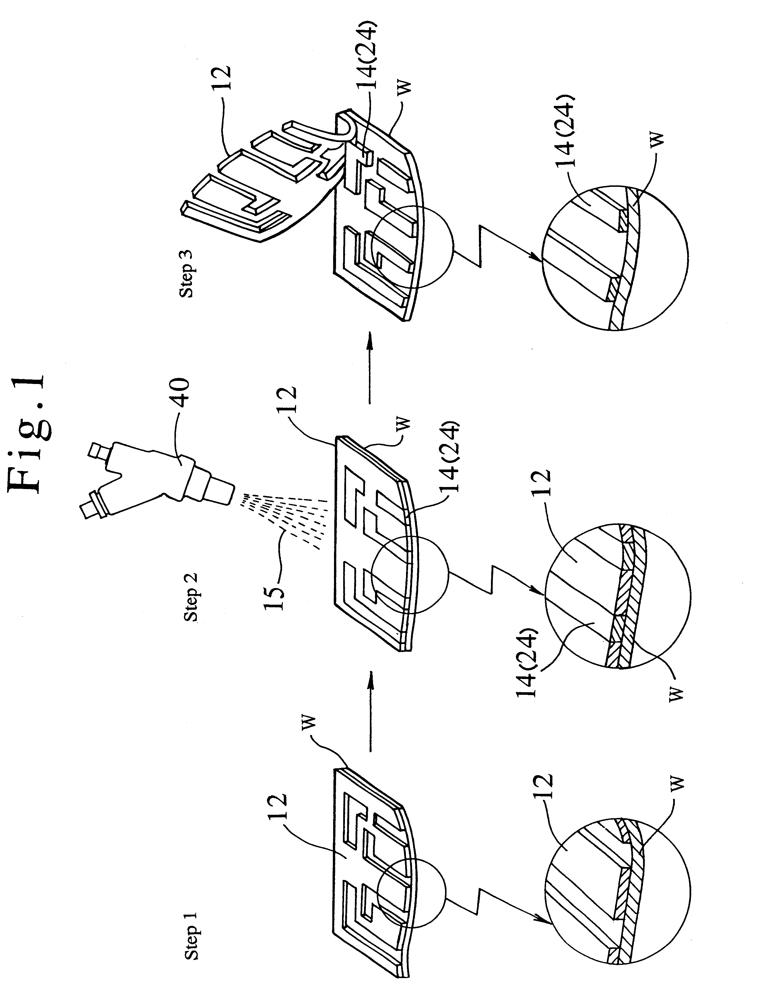
This application is shown by the example, where silver coat 24 having a predetermined pattern was formed on the surface of ceramic substrate as a workpiece W by means of method in accordance with the present invention, and a printed circuit was formed by utilizing the silver coat 24.

As shown in FIG. 1, in this application, the surface of ceramic substrate was covered with a masking material 12 at its part where the silver coat 24 was not to be formed. Thus, the silver coat 24 was not formed on the masked part of surface.

Then, silver powders each having the average particle size of 45.mu. and the shape of substantial sphere were ejected to the partly mas...

example 1

After sandblasting with WA powders #220, coat was formed with metallic powders stated below, and then, masking material was removed.

example 2

After sandblasting with WA powders #220, masking material was removed and then, coat was formed with metallic powders stated below.

The thickness of coat formed on the above blast worked surface was thick or large. On the other hand, that of coat formed on the surface covered with the masking material was thin or small. Accordingly, on the engraved (sandblast worked) surface of glass, light and shade of color as well as stereoscopic view could be expressed.


PUM

PropertyMeasurementUnit
ejection pressureaaaaaaaaaa
ejection velocityaaaaaaaaaa
particle sizeaaaaaaaaaa

Abstract

Method for forming metallic coat where, the surface of workpiece is partly covered with a masking material having a predetermined pattern, and metallic powders are ejected to the surface at the ejection velocity of 80 m / sec or higher or at the ejection pressure of 0.3 Mpa or higher by utilizing an ejection apparatus such as blast work apparatus, in order to easily attain the metallic coat having high adhesion strength without washing process, nor heat process by a relatively simple facility.

Description

1. Field of the InventionThis invention generally relates to a method for forming metallic coat or layer on the surface of workpiece. More concretely, this invention relates to a method for forming metallic coat which can be applied in various kinds of technical field, e.g. forming of printed circuit, ceramic, ceramics, ceramic product, metal tableware, several kinds of thermosetting resin molding product, surface decoration for a paper and the like having at least enough thickness to allow the ejection of metal powders without making a through hole thereon.Further, this invention relates to a method for forming metallic coat on the surface of workpiece at its predetermined part, and for nitriding in general meaning including soft nitriding the surface of workpiece at its rest part, by coating the above predetermined part with the metallic coat formed by the above method, before nitriding, so that the above coated predetermined part is prevented from being subjected to nitriding.2. ...

Claims


Application Information

Patent Timeline
Patent Type & Authority Patents(United States)
IPC IPC(8): C23C24/00C23C8/04C23C24/04
CPCC23C8/04C23C24/04H05K2203/0191
Inventor MIYASAKA, YOSHIO
Owner FUJI KIHAN CO LTD
Learn More