
Method and facility for producing reduced iron

Inactive Publication Date: 2001-09-04
SUMITOMO METAL IND LTD
View PDF12 Cites 32 Cited by
  • Summary
  • Abstract
  • Description
  • Claims
  • Application Information

AI Technical Summary

Problems solved by technology

The conventional process of producing reduced iron as disclosed in U.S. Pat. No. 3,443,931 described above (for the sake of convenience, referred to as "pelletizing process" hereinafter) has fundamental problems as follows:
1) As an agglomerate (pellet) as merely agglomerated does not have sufficient physical strength to withstand handling during the process, it requires drying before charged into a reduction furnace. This entails installation of a drying unit in addition to a pelletizing furnace of complex construction, involving fairly high costs of operation and maintenance thereof. Furthermore, owing to a longer time required in the process from a step of drying the pellet to completion of a reduction step, production efficiency of the process is low, and it is difficult to hold down a cost of producing reduced iron.
2) It is impossible to avoid generation of particles outside a predetermined size range during the pelletizing process. As it is necessary to recycle undersize particles to a mixing step, and to crush oversize particles before recycling to the mixing step, the production efficiency is poor.
3) Iron oxides generated at steel mills such as iron-bearing dust, sludge, scale, and the like are among precious ferrous materials, however, these are often found in lumpy form when recovered, composed of fine particles bonded together, or in a form too large as pellet feed as in the case of scales. Accordingly, for pelletizing these iron oxides on their own in place of iron ore fine, or in admixture with iron ore fine, it is necessary to pulverize them to a predetermined size beforehand, necessitating installation of a pulverizing apparatus.
The process disclosed in the Japanese Patent Laid-open No. 7-238307 described above, however, belongs to a category of the pelletizing process consisting of steps of mixing, agglomeration, and drying, hardly solving the problems of the pelletizing process described above.
The conventional process of producing reduced iron described above, however, has the following problem.
Then, generated fines are blown off by a combusting gas, and adhered in a molten condition to the wall of the furnace, causing troubles to facilities.
In addition, the generated fines adhere in a molten condition to the rotary hearth, erode the hearth and roughen the surface of it.
Further, nonuniformity in firing results due to lack of uniformity in the size of the agglomerates, leading to the need of lengthening a firing time required for producing reduced iron of 92% metallization ratio, lowering productivity in producing the reduced iron.
Addition of the binder described above for prevention of an adverse effect of powdering of the agglomerates has been found effective to an extent, however, not successful in complete prevention of the powerdering.
Furthermore, use of organic binders, which are expensive, results in a higher cost of production while use of inorganic binders having a constituent other than iron, that is, a slag constituent, has a drawback of degrading the quality of the reduced iron.
As described in the foregoing, the conventional pelletizing process has a number of problems.
Firstly, the blast furnace process has a drawback of requiring lumpy ferrous raw material and coke. In this process, cokes are formed in coke ovens through carbonization of coal, and only lumpy cokes are used after screening. Deposits of hard coking coal for use in making cokes are unevenly distributed in geographical terms. In addition, other major problems with the process are huge capital outlay required in replacing the old coke ovens, and needs for prevention of air pollution caused by operation of the coke ovens. With respect to ferrous raw material, fine iron ores need to be agglomerated into pellets or sinters for use in the process except the case where lumpy ores are used. In view of a tight supply position of lumpy iron ore, and high costs of pellets, however, use of sinters has come to be in the mainstream of the steel industry's practice in Japan, but countermeasures for prevention of air pollution caused by sintering operation poses a major problem to the industry.
In the process of producing hot metal in the shaft reduction furnace, coke is not required, however, the process has a problem of requiring lumpy iron ore as ferrous raw material as in the case of the blast furnace process.
A process described in Japanese Patent Publication No. 3-60883 is considered effective, however, has a drawback that fine iron oxides and powdery solid reductants need to be mixed and agglomerated before being charged into a reduction furnace.
Accordingly, undersize particles are sent straight to a mixing step while oversize particles need to be crushed before recycled to the mixing step, deteriorating efficiency of the process.
In addition, since agglomerates as merely agglomerated do not have sufficient strength to withstand handling, the agglomerates need to be dried before charged into the reduction furnace, entailing installation of a drying unit in addition to an agglomeration plant.
All these factors add up the production cost of reduced iron.
Furthermore, time required for agglomeration and drying is relatively long in comparison with that for reduction, adversely affecting the efficiency of a plant as a whole.

Method used


Image

  • Method and facility for producing reduced iron
  • Method and facility for producing reduced iron
  • Method and facility for producing reduced iron

Examples


example 1

Powder ferrous raw material, coal (fine powder coal) as powder solid reductant and bentonite (binder) each of a composition shown in Table 1-Table 3 were prepared. Table 4 shows the grain size constitution of the powder ferrous raw material and the coal.

TABLE 1

TABLE 1

TABLE 4

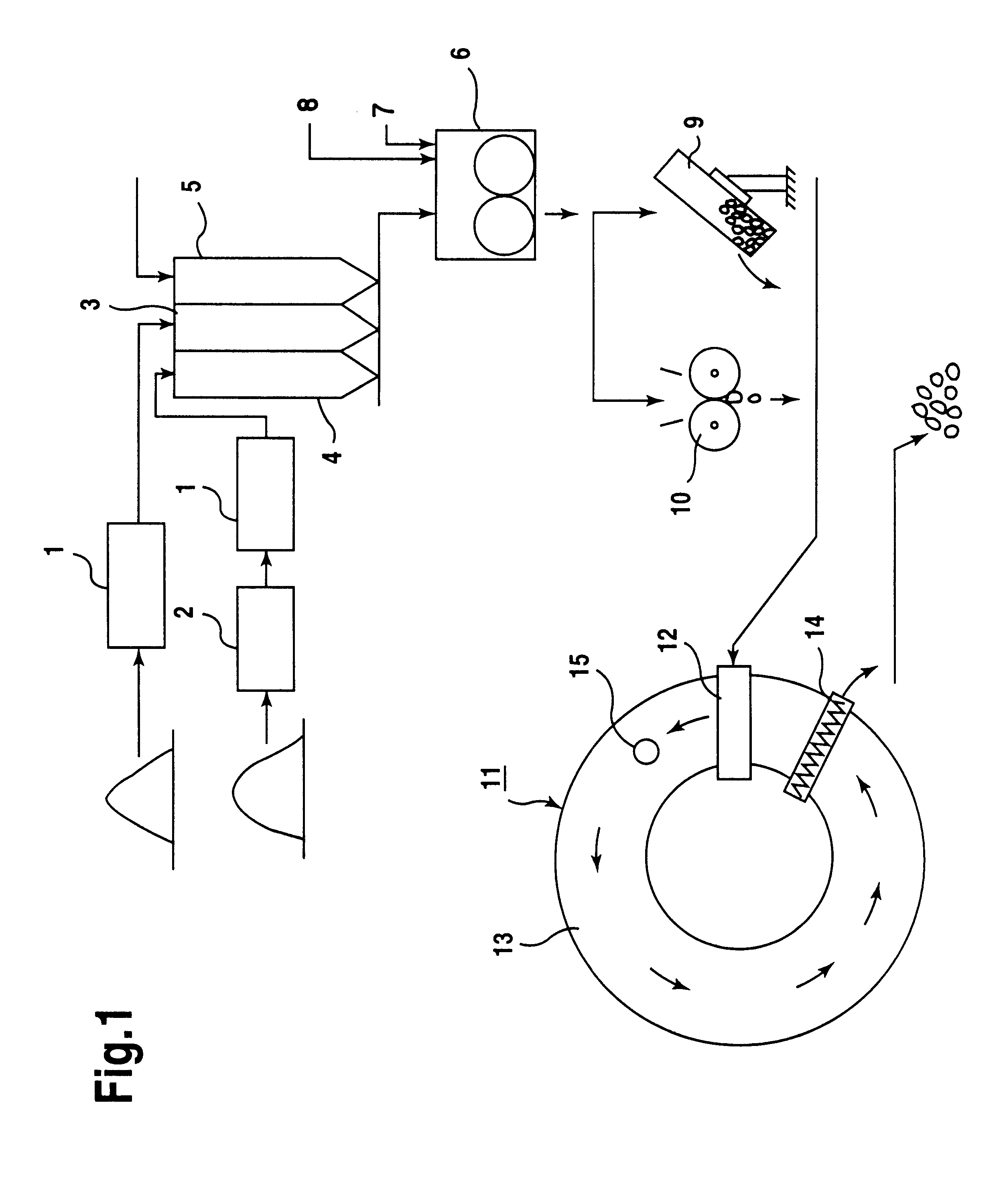
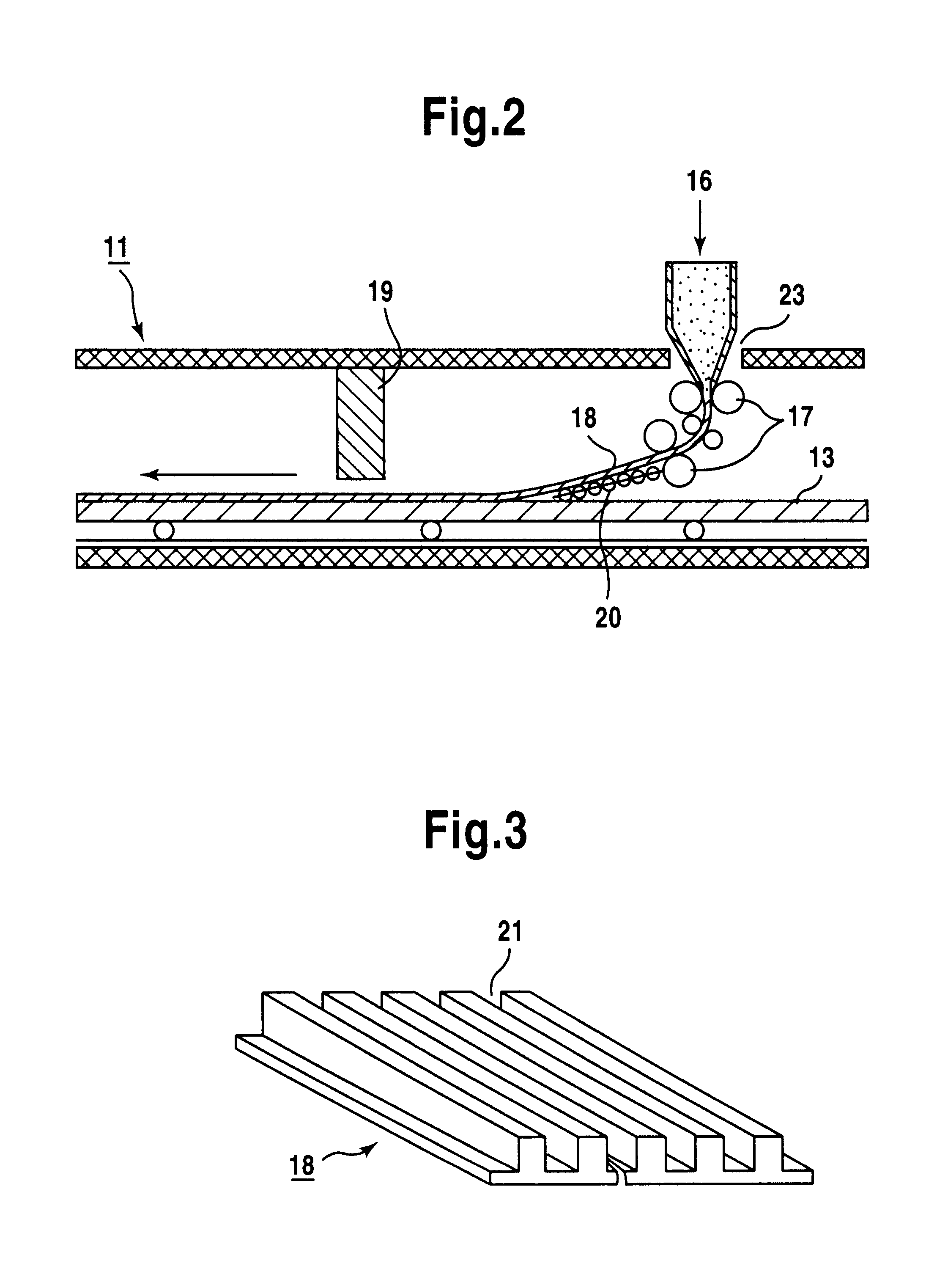
After mixing them in blending ratios shown in Table 5, the mixed raw materials were formed into sheet-like compacts each of 15 mm thickness and 500 mm width and into sheet-like compacts having the same width but having uneven shape on the surface as shown in FIG. 3 by a shaping and charging device shown in FIG. 2.

Further, for the comparison, a portion of the mixed raw materials was pelletized into green pellets of 18 mm diameter by a pan type pelletizer, and then heated to 115.degree. C., into dry pellets with 90% or more of water content being removed.

The compacts and pellets were put to reducing test under the conditions shown in Table 6 by using a small-sized high temperature heating-reduction test furnace sho...

case 7

is an example of using ferrous raw material comprising ore A blended with igron work dust. Case 8 is an example of using ferrous raw material comprising dust and mill scale blended therewith. The reduction time in each of the cases was about 12 min and 11 min, which was substantially identical with the case 4 of using iron ore.

Further, dezinc ratio in case 7 using Zn-containing dust was about 92% and the dezinc effect according to the method of the present invention could be confirmed.

It is considered that although the mixed raw material S was somewhat coarser, the reduction time was not changed so much in case 8, because iron oxide in the mixed raw material S was FeO and the reduction ratio was about 30% on the basis of Fe.sub.2 O.sub.3, so that the reduction amount down to the metallic iron may be smaller as well as that the amount of endothermic reduction per iron atom from FeO into metallic iron is decreased by about 20590 kcal / kmol compared with the case of Fe.sub.2 O.sub.3 and...

example 2

Powder iron ore and coal (fine powder coal) as the powder solid reductant having the composition and the grain size constitution as shown in Table 7-Table 9 blended in a blending ratio shown in Table 10 was prepared.

TABLE 7

TABLE 9

TABLE 9

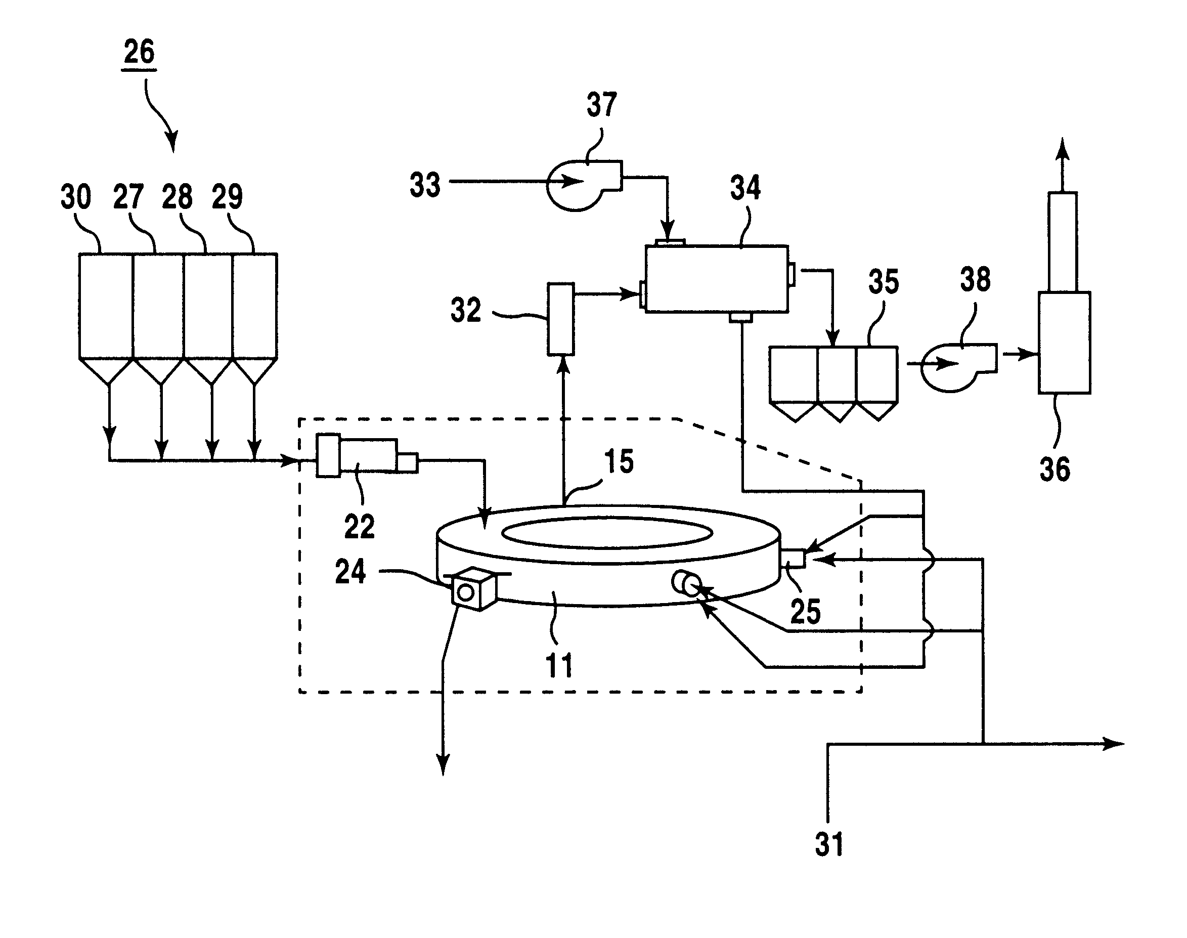
As the test facility, a small-sized molten iron manufacturing test facilities described above shown in FIG. 17 was used. That is the facility comprises a rotary hearth furnace 11 as a preliminary reduction furnace, a shaft furnace 85 as a smelting furnace and a raw material receiving hopper 26, a mixer 22 and a waste heat recovery heat exchanger 34 and the like.

Powder ore 27, reductant 28 (fine powder coal) and a binder 29 received in a raw material receiving hopper 26 were taken out each by a predetermined amount from respective hoppers and charged in the mixer 22, sufficiently mixed with addition of a small amount of water and then the mixture was charged into the rotary hearth furnace.

The mixture was charged into the hearth by compacting them into...


PUM

PropertyMeasurementUnit
temperatureaaaaaaaaaa
diameteraaaaaaaaaa
diameteraaaaaaaaaa

Abstract

In the method of producing reduced iron according to the invention, fine iron oxides and powdery solid reductants are mixed, compacted into sheet-like compacts, and charged onto the hearth of a reduction furnace for reduction while maintaining the temperature inside the furnace at not less than 1100° C. As the sheet-like compacts can be obtained by compacting mixture of raw material by use of rollers or the like, processing time is much shorter than the case of pelletization or agglomeration. A drying step is unnecessary since feeds are placed no the hearth via a feeder chute or the like. The method is carried out with ease by use of the facility according to the invention. High quality hot metal can be produced by charging reduced iron in hot condition obtained by the method described as above into a shaft furnace or a in-bath smelting furnace for melting at high thermal efficiency.

Description

The present invention broadly relates to production of reduced iron, and production of hot metal therefrom. More particularly, the present invention is concerned with a method of and a facility for producing reduced iron by compacting fine iron oxides, for example, fine iron ore, iron-bearing dust, sludge, scale, and the like which are generated at steel mills, in admixture with powdery solid reductants, for example, coal, charcoal, petroleum cokes, cokes, and the like, into sheet-like shape without agglomerating aforesaid raw materials, and by charging sheet-like compacts into a heated furnace for reduction at a high temperature, and further, with an method of producing hot metal by charging the reduced iron kept in a hot condition into a shaft furnace or a in-bath smelting furnace.BACKGROUND TECHNOLOGYWith recent growth in production of steel products by means of electric furnaces, much attention has been drawn to a technology of obtaining ferrous material as a feed therefor by so...

Claims


Application Information

Patent Timeline
Patent Type & Authority Patents(United States)
IPC IPC(8): C22B5/00C22B5/10C21B13/00C21B13/10C22B1/14C22B1/24
CPCC21B13/0046C21B13/10C22B5/10C22B1/24C21B13/105Y02P10/134C21B11/00C21B11/02C22B1/14
Inventor KAMEI, YASUOKAWAGUCHI, TAKAZOYAMAOKA, HIDEYUKINAKAMURA, YOSHIHISA
Owner SUMITOMO METAL IND LTD
Learn More