
Long cycle-life alkali metal battery

a technology of alkali metal batteries and cycle life, applied in the direction of secondary cell charging/discharging, non-aqueous electrolyte cells, positive electrodes, etc., can solve the problems of short cycle life, insufficient cycle life and safety of these batteries, and low charge rate, so as to achieve fast charge rate and improve cycle life , the effect of long cycle li

Inactive Publication Date: 2001-03-20
RAMOT UNIV AUTHORITY FOR APPLIED RES & INDAL DEVMENT
View PDF4 Cites 199 Cited by
  • Summary
  • Abstract
  • Description
  • Claims
  • Application Information

AI Technical Summary

Benefits of technology

It is an object of the present invention to provide an alkali metal secondary electrochemical cell with a long cycle life and a fast charge rate. A more particular object of the invention is to provide a rechargeable lithium battery exhibiting superior cell performance as compared to such cell systems known in the art.
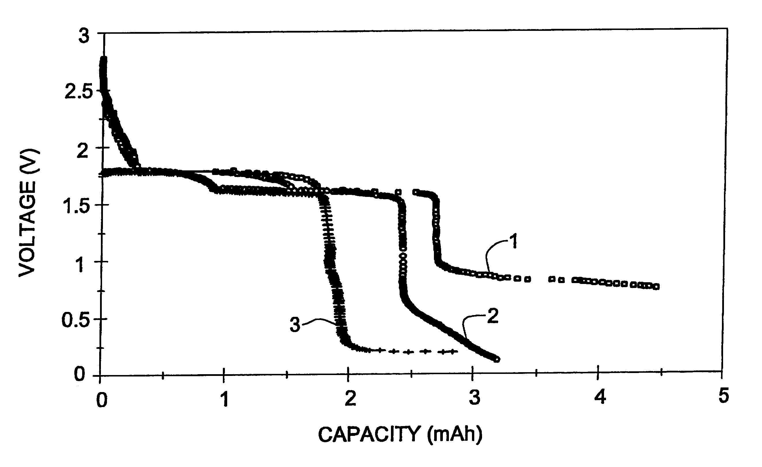
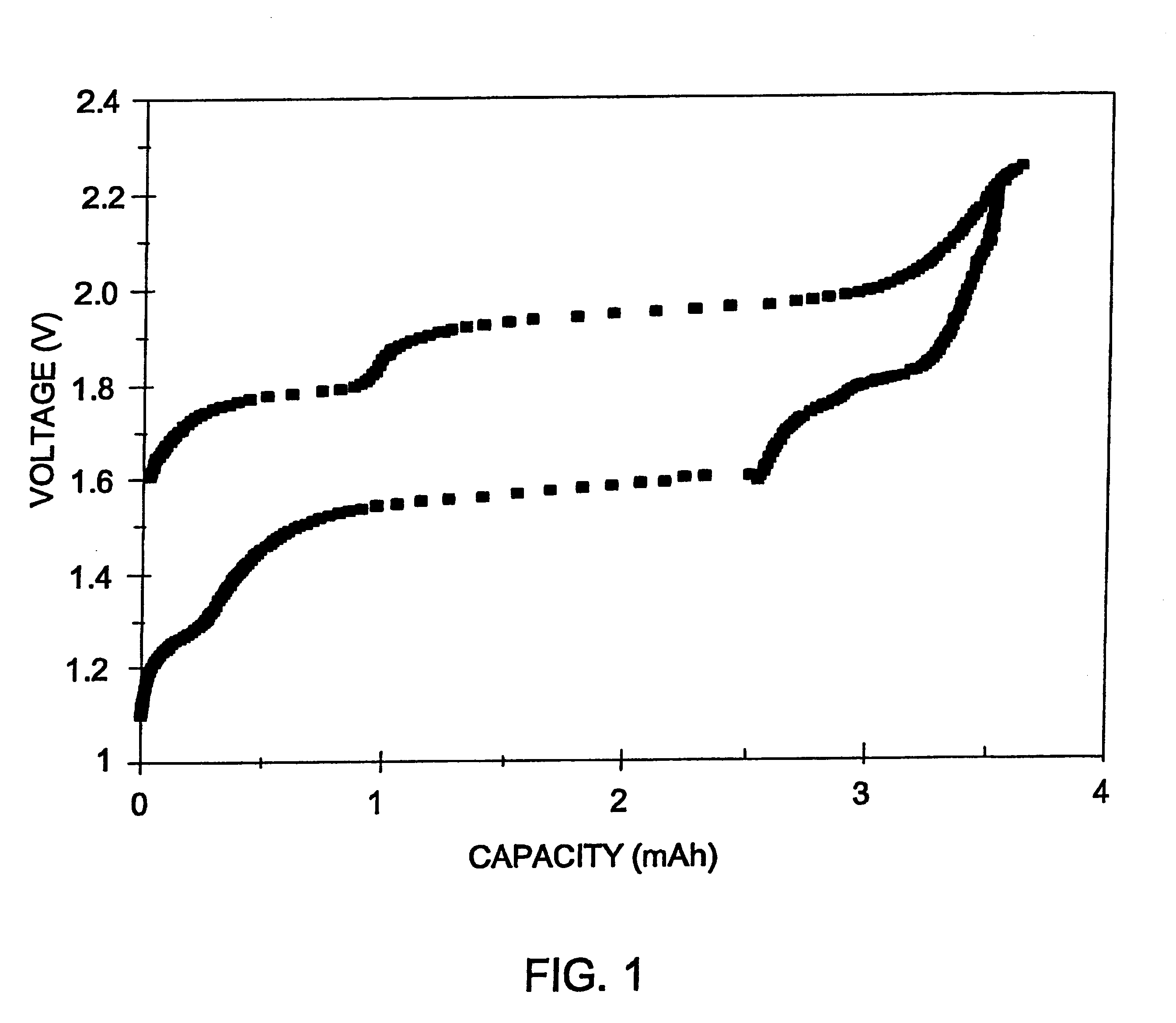
From the experimental data obtained it may be concluded that the formation of a protective film on the surface of a cathode, brings about to a low capacity fading and may lead to an improved shelf life. In addition it provides improved protection to a lithium battery during wide temperature range operations.

Problems solved by technology

These cells, however, suffer from two main drawbacks: slow charge rate and short cycle life.
However the cycle life and safety of these batteries, are insufficient.
One of the main reasons for the decreased reversibility of these lithium batteries is non-compatibility of the cathode active material with the non-aqueous or polymer electrolytes.
The final product of fully reduced cathode material is atomic metal, usually in the form of small aggregates having a large surface area, which are excessively reactive and, therefore, highly susceptible to attack by the electrolyte components causing the electrolyte decomposition and the formation of undesirable products.

Method used


Image

  • Long cycle-life alkali metal battery
  • Long cycle-life alkali metal battery
  • Long cycle-life alkali metal battery

Examples


example 2

A Li / CPE / FeS.sub.2 cell with a 7 .mu.m thick film composite cathode was prepared and assembled as described in Example 1, starting with the following starting materials: 3.3 mg LiI, 21.6 mg P(EO), 4.1 mg EC and 100.8 mg FeS.sub.2. For the preparation of ultra tin cathodes, 7 .mu.m pristine pyrite powder was used. This powder was prepared by ball milling the pristine pyrite for 48 hours. In order to prepare a cathode with good mechanical properties and having a good contact with the polymer electrolyte, the polymer electrolyte was casted directly onto the composite cathode film. The resultant two-layered film was placed between the Li anode and the graphite current collector. The SEI was built twice during the first and fifth cycles at 200 .mu.A / cm.sup.2 down to 0.8 V. The total SEI formation capacity was 1.5 mAh. The cell went through over 420 reversible cycles (100% DOD), and the degree of degradation did not exceed 0.11% / cycle. (FIG. 3).

example 3

A Li / CPE / FeS.sub.2 cell with a 7 .mu.m thick film composite cathode was prepared and assembled as described in Example 2. The SEI was built during the first discharge at 50 .mu.A / cm.sup.2 down to 0.76 V. The SEI formation capacity was 1.76 mAh / cm.sup.2. The cell went through over reversible 290 cycles (100% DOD), with the degree of degradation being 0.19% / cycle. (FIG. 3)

example 4

A Li / CPE / FeS.sub.2 cell with a 7 .mu.m thick film composite cathode was prepared as described in Example 2. The SEI was formed twice, during the first discharge at 50 .mu.A / cm.sup.2 and the fifth discharge at 200 .mu.A / cm.sup.2 down to 0.815 V. The SEI formation capacities were 1 and 0.5 mAh / cm.sup.2, respectively. The cell went through over 235 reversible cycles (100% DOD), and the degree of degradation did not exceed 0.16% / cycle (Table 1, FIG. 3)


PUM


Abstract

The present invention provides a cathode for use in a secondary electrochemical cell, such cathode being coated with a very thin, protective film, permeable to ions. The protective film of the cathode usually has a thickness of up to about 0.1 mum and it provides protection against high voltage charging and overdiscbarging. The present invention further provides a secondary electrochemical cell comprising such a cathode.

Description

This invention relates to electrochemical cells, especially to rechargeable cells, having an anode consisting of an alkali metal or alkali metal alloy, particularly a lithium anode. The invention also relates to cathodes for use in such electrochemical cells.Recently, with the increased awareness of air pollution and global warming, the development of electric vehicles has gained considerable interest, thus leading to a need for improvements in the performance of secondary batteries. Of specific interest are batteries, which can be minaturized, have a high energy density and which demonstrate a long cycle life.Non-aqueous electrolyte batteries containing anodes composed of alkali metals such as lithium are an example of known batteries that meet these criteria. Lithium batteries have recently undergone remarkable developments in terms of performance improvement and miniaturization. These developments have required improvements with respect to the material and shape of the anodes and...

Claims


Application Information

Patent Timeline
IPC IPC(8): H01M4/58H01M2/14H01M4/02H01M4/04H01M4/131H01M4/136H01M4/1391H01M4/1397H01M4/36H01M4/587H01M4/62H01M4/66H01M10/0525H01M10/0566H01M10/0568H01M10/0569H01M10/36
CPCH01M4/0445H01M4/045H01M4/131H01M4/136H01M4/1391H01M4/1397H01M4/366H01M4/5815H01M4/587H01M4/623H01M4/663H01M4/667H01M10/0525H01M10/0566H01M10/0568H01M10/0569H01M4/405H01M4/621H01M4/661H01M10/44H01M2004/028H01M2300/0094Y02E60/122Y02E60/10
Inventor PELED, EMANUELGOLODNITSKY, DIANASTRAUSS, ELA
Owner RAMOT UNIV AUTHORITY FOR APPLIED RES & INDAL DEVMENT
Learn More