
Method and device on printed boards

a printed board and method technology, applied in resistive material coatings, circuit masks, non-metallic protective coating applications, etc., can solve problems such as deterioration of soldering quality, printed board becomes the subject of complaint, and impaired soldering joints

Inactive Publication Date: 2001-01-16
TELEFON AB LM ERICSSON (PUBL)
View PDF8 Cites 22 Cited by
  • Summary
  • Abstract
  • Description
  • Claims
  • Application Information

AI Technical Summary

Benefits of technology

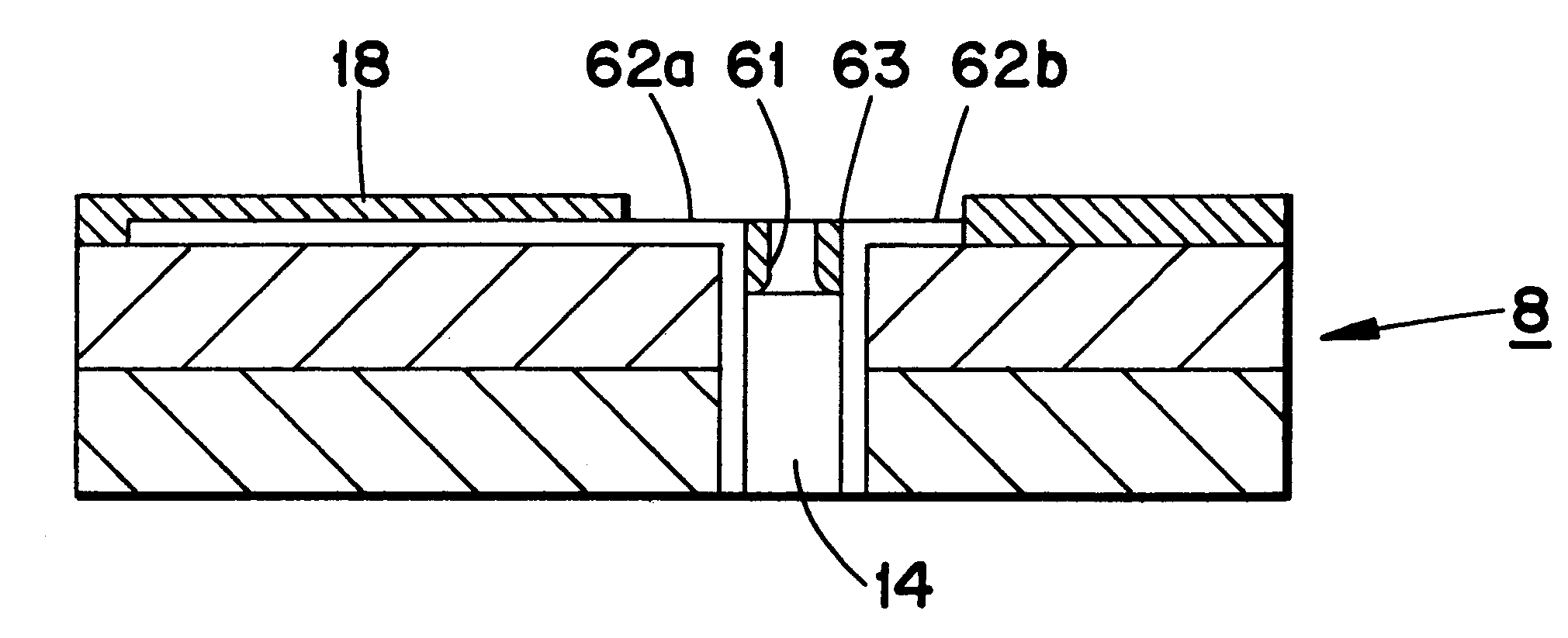
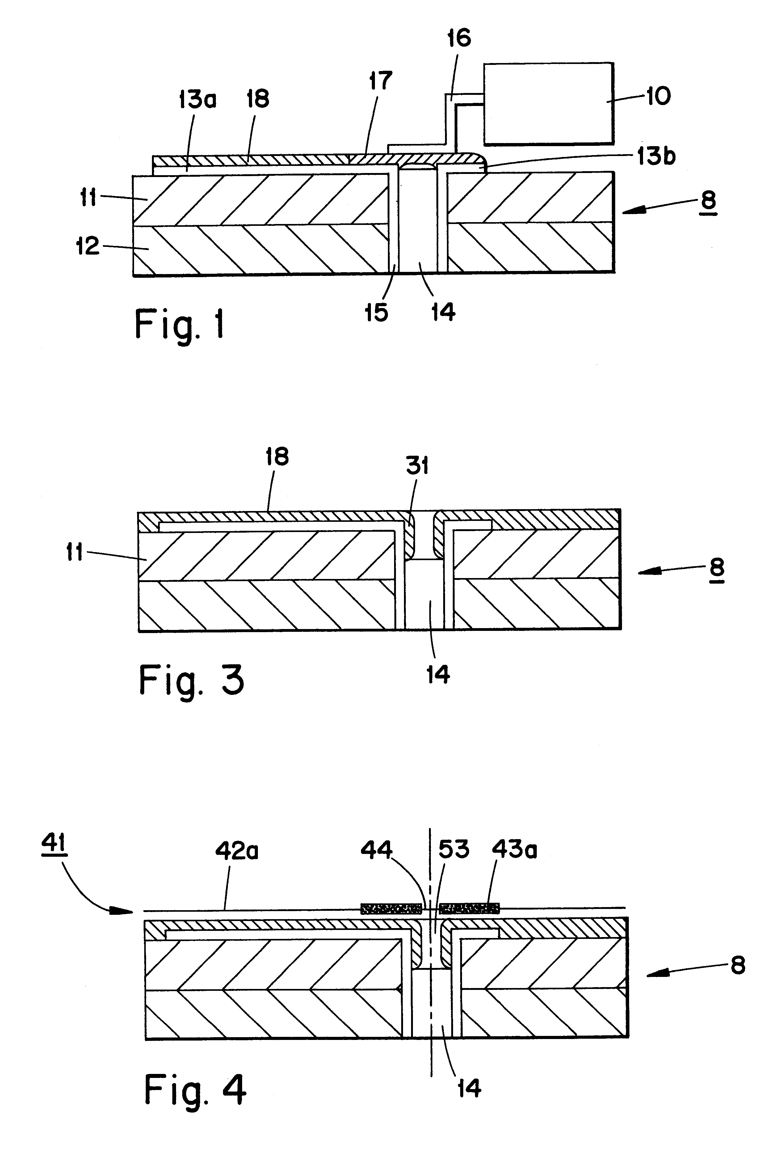
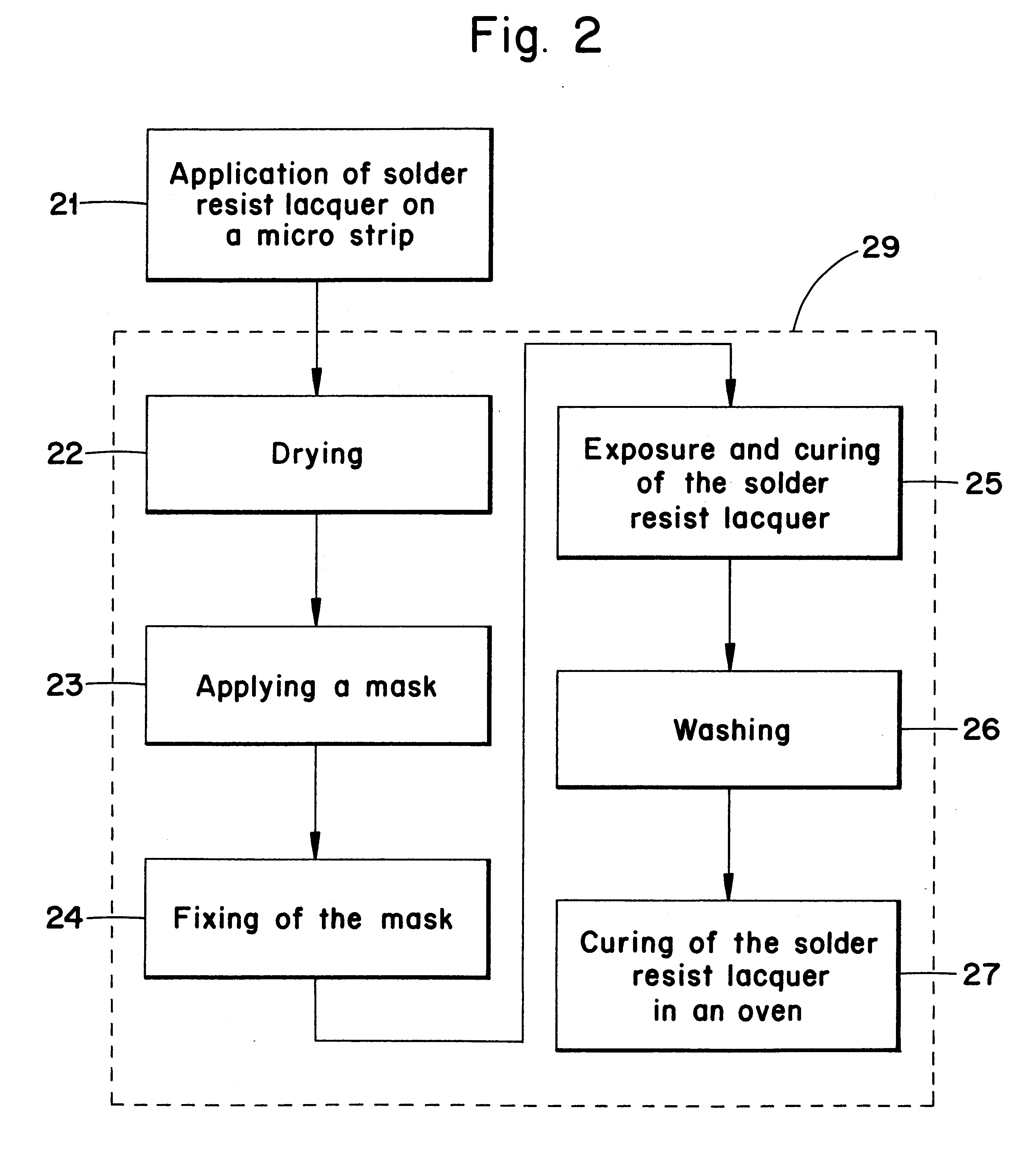
The invention gives a method, a device which is used during the method and a solder stop for solving said problems. The inventive idea is that by using the earlier mentioned disadvantage where solder resist lacquer in certain situations flows down into the through-holes, through influencing the viscosity of the solder resist lacquer so that a certain quantity of lacquer intentionally flows down into the through-holes. The lacquer in the hole cures and forms a solder stop in the through-holes. Said solder stop thereby prevents the liquid solder from passing through the through-hole by the solder stop made of solder resist lacquer preventing the solder from flowing down and wetting the walls of the through-hole.
The advantages of the present invention is that it is simple and very cheap to perform. The invention can be performed with existing equipment and as a part of already known production steps, which means that it does not take any extra time in the manufacturing process. The invention is suitable both for small series production and for mass production. No extra material is required to be inserted in the through-hole in order to prevent the solder from passing through the through-holes.

Problems solved by technology

This is considered to be a big disadvantage and an example of bad process control, whereby the printed board becomes the subject of a complaint.
The soldered joints are thereby impaired.
More precisely, the problem occurs in the case where the solder on a printed board assembly during re-flow soldering becomes liquid and flows down in the through-holes.
This means that the quality of the soldering deteriorates.
A similar problem occurs during wave soldering and drag soldering, where the solder can unintentionally climb up into the through-holes.
The inventive idea is that by using the earlier mentioned disadvantage where solder resist lacquer in certain situations flows down into the through-holes, through influencing the viscosity of the solder resist lacquer so that a certain quantity of lacquer intentionally flows down into the through-holes.

Method used


Image

  • Method and device on printed boards
  • Method and device on printed boards
  • Method and device on printed boards

Examples


Embodiment Construction

As mentioned earlier, solder resist lacquer is used to protect the electrically conducting surfaces on a printed board against moisture and corrosion and to limit the spreading of the solder along the conducting surfaces. Three common methods for applying solder resist lacquer on a surface of a printed board product are curtain coating, electrostatic coating and screen printing.

Photopolymeric coating or silk screen printing means that a solder resist lacquer is screen printed onto the surface of the product. A silk screen template is produced with the help of a photographic method. The template is placed over the printed board product before the lacquer or paint is poured over the template. With the help of a rubber rake the lacquer or paint is pressed through the template down onto the printed board product.

Curtain coating means that the product passes a curtain of photographically sensitive lacquer which covers the whole surface of the product. The thickness of the lacquer on the ...


PUM

PropertyMeasurementUnit
distanceaaaaaaaaaa
speedaaaaaaaaaa
electrically conductingaaaaaaaaaa

Abstract

The present invention relates to a solder stop in through-plated through-holes on micro strip boards (8). A solder resist lacquer (18) with a certain viscosity is applied on a micro strip board (8) wherein the solder resist lacquer (18) flows out over the micro strip (8) and down into a top portion of the through-plated through-hole and dried. A ring-shaped portion of the solder resist lacquer (18) is retained in the top part of the through-plated through-hole.

Description

THE FIELD OF THE INVENTIONThe present invention relates to a method and a device for manufacturing of solder stops in plated through-holes in printed boards and a solder stop for improving the solder quality in soldering connected to through-holes.STATE OF THE ARTA product which consists of an electrically insulated material with a pattern of an electrically conducting material, e.g. a printed board, often comprises a protective layer of lacquer on predetermined surfaces of the product. In the case that only certain parts of the pattern are to be coated with solder, then the other parts are delimited or covered with a so-called solder resist lacquer. The lacquer prevents on the one hand that bridges of solder occur between adjacent electrically conducting surfaces and on the other hand that solder flows out along the pattern. The solder resist lacquer also function as an insulating protection against moisture, particles, components and corrosion which can damage the electrically con...

Claims


Application Information

Patent Timeline
Patent Type & Authority Patents(United States)
IPC IPC(8): H05K3/34H05K3/00H05K1/11H05K1/02H05K3/28H05K3/42
CPCH05K1/113H05K3/0094H05K3/3452H05K1/0237H05K3/0082H05K2201/09581H05K2203/0759
Inventor BERGSTEDT, LEIF ROLAND
Owner TELEFON AB LM ERICSSON (PUBL)
Learn More