
Manufacturing method of protective-component-provided workpiece

Pending Publication Date: 2022-11-17
DISCO CORP
View PDF0 Cites 0 Cited by
  • Summary
  • Abstract
  • Description
  • Claims
  • Application Information

AI Technical Summary

Benefits of technology

The present invention relates to a method of making a protective-components workpiece by melting thermoplastic resin onto one surface of the workpiece to form a layer that becomes the protective component. The problem addressed in the invention is the shrinkage of the sheet due to cooling and the variation in the thickness and size of the sheet, which makes it difficult to form the sheet into a uniform size without variation and bends the workpiece due to the shrinkage of the sheet. The invention provides a solution by using ultraviolet rays to cur a mixed resin made of a thermoplastic resin and a liquid ultraviolet-curable resin, which reduces shrinkage of the sheet and reduction in variation in the thickness and size of the sheet. The resulting protective component is close contact with one surface of the workpiece and protects it.

Problems solved by technology

When the glue layer of the adhesive tape is brought into close contact with the surface of the workpiece to be held and is stuck thereto, there is a problem that a residue of the adhesive is left on the workpiece when the adhesive tape is separated from the workpiece.
Further, due to action of the glue layer as a cushion, the workpiece becomes more likely to vibrate in processing.
As a result, there is a problem that breakage may possibly occur in the workpiece or chips obtained by dividing the workpiece may possibly be scattered.
However, a heating time of several tens of seconds to several tens of minutes is required to form the thermoplastic resin into a uniform layer with application of heat and pressure, leading to a decrease in efficiency.
However, even in the case of forming the sheet by the thermoplastic resin through application of heat and pressure, the sheet shrinks in cooling, and the thickness and size of the sheet change.
This leaves problems that it is difficult to form the sheet into a uniform size without variation and that the workpiece bends due to the shrinkage of the sheet.

Method used


Image

  • Manufacturing method of protective-component-provided workpiece
  • Manufacturing method of protective-component-provided workpiece
  • Manufacturing method of protective-component-provided workpiece

Examples


first embodiment

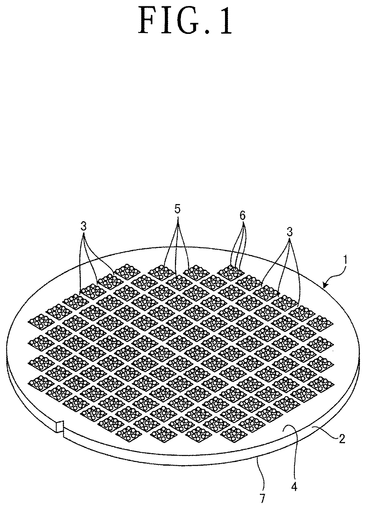
[0034]A manufacturing method of a protective-component-provided workpiece, a processing method of a workpiece, and a protective component for a workpiece according to a first embodiment of the present invention will be described based on drawings. FIG. 1 is a perspective view illustrating a workpiece 1 that is a subject of the manufacturing method of a protective-component-provided workpiece, the processing method of a workpiece, and the protective component for a workpiece according to the first embodiment. In the first embodiment, the workpiece 1 is a wafer such as a circular plate-shaped semiconductor wafer or optical device wafer and includes, as a substrate 2, silicon, sapphire, gallium arsenide, an SiC substrate, a GaN substrate, a lithium tantalate (LT) substrate, a single-crystal diamond substrate, or the like. Note that the workpiece 1 is not limited to the circular plate-shaped workpiece in the present invention and may be a resin package substrate, a metal substrate, or a...

second embodiment

[0092]A manufacturing method of a protective-component-provided workpiece, a processing method of a workpiece, and a protective component for a workpiece according to a second embodiment of the present invention will be described based on drawings. FIG. 15 is a sectional view for explaining a protective-component-provided workpiece forming step 1004 that is included in the manufacturing method of a protective-component-provided workpiece according to the second embodiment. FIG. 16 is a perspective view illustrating a protective-component-provided workpiece 130 manufactured by the manufacturing method of a protective-component-provided workpiece according to the second embodiment. Note that, in FIG. 15, diagrammatic representation of the bumps 6 is omitted. In FIG. 15 and FIG. 16, the same part as the first embodiment is given the same reference sign, and description thereof is omitted.

[0093]The manufacturing method of a protective-component-provided workpiece according to the second...

third embodiment

[0103]A manufacturing method of a protective-component-provided workpiece, a processing method of a workpiece, and a protective component for a workpiece according to a third embodiment of the present invention will be described based on drawings. FIG. 17 is a sectional view for explaining a resin layer forming step 1002 and a protective component forming step 1003 that are included in the manufacturing method of a protective-component-provided workpiece according to the third embodiment. FIG. 18 is a sectional view for explaining a protective-component-provided workpiece forming step 1004 that is included in the manufacturing method of a protective-component-provided workpiece according to the third embodiment. Note that, in FIG. 18, diagrammatic representation of the bumps 6 is omitted. In FIG. 17 and FIG. 18, the same part as the first embodiment and the second embodiment is given the same reference sign, and description thereof is omitted.

[0104]The manufacturing method of a prot...


PUM


Abstract

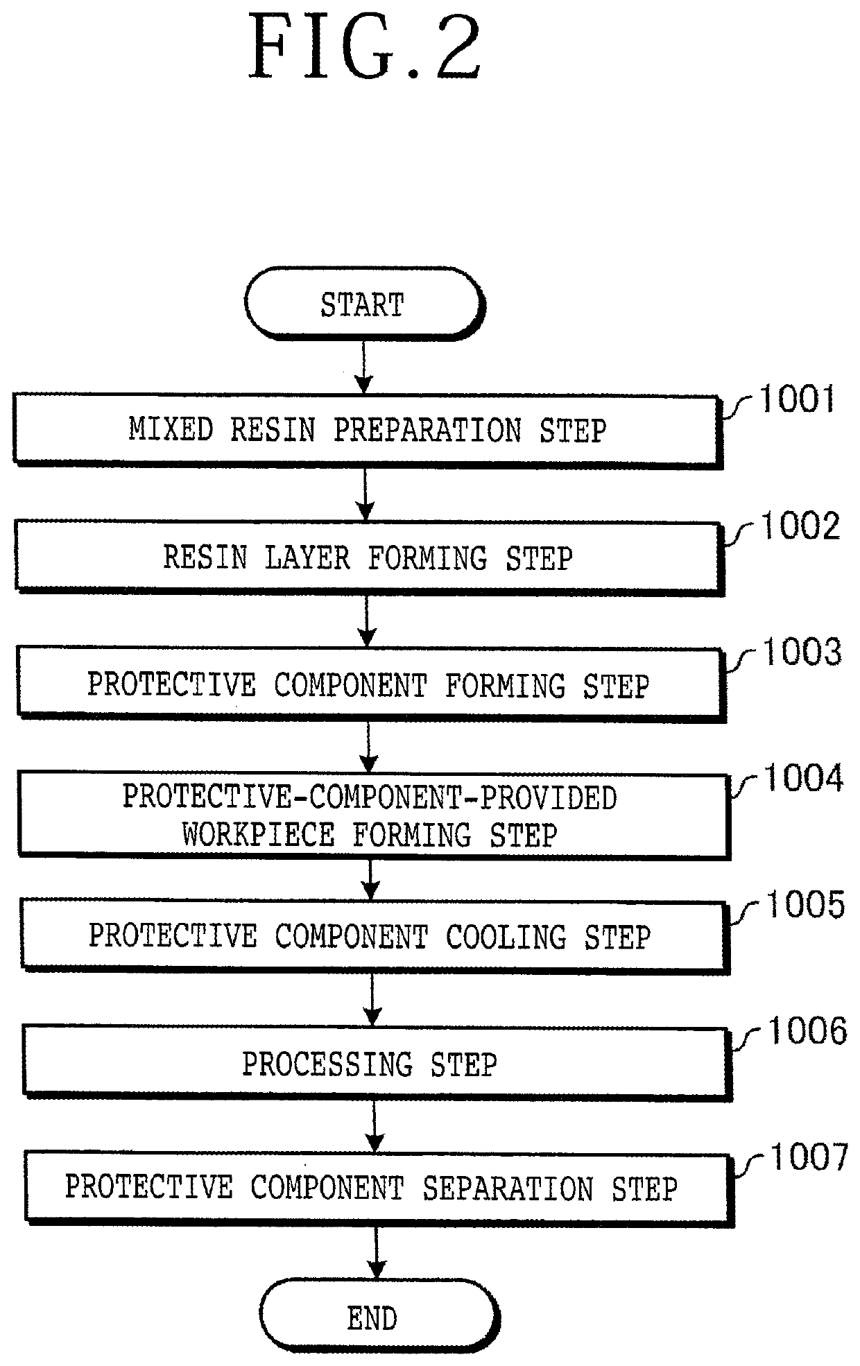
There is provided a manufacturing method of a protective-component-provided workpiece. The manufacturing method of a protective-component-provided workpiece includes a step of dissolving a thermoplastic resin whose solubility parameter is equal to or higher than 8.5, in a liquid ultraviolet-curable resin, to prepare a liquid mixed resin, a step of supplying the mixed resin to a support surface of a support table to form a resin layer with a predetermined thickness, a step of irradiating the resin layer with ultraviolet rays and curing the resin layer to form a protective component with a sheet shape, and a step of heating the sheet-shaped protective component before or after one surface of the sheet-shaped protective component and one surface of the workpiece are brought into close contact with each other, and causing the sheet-shaped protective component to come into close contact with the workpiece and integrate with the workpiece.

Description

BACKGROUND OF THE INVENTIONField of the Invention[0001]The present invention relates to a manufacturing method of a protective-component-provided workpiece, a processing method of a workpiece, and a protective component for a workpiece.Description of the Related Art[0002]When various plate-shaped workpieces such as a semiconductor wafer, a resin package substrate, a ceramic substrate, and a glass substrate are ground to be thinned by a grinding apparatus or are divided by a cutting blade or a laser beam, the workpieces are held under suction by a chuck table. In order to prevent damage, contamination, and so forth of the workpiece caused when a surface of the workpiece to be held by the chuck table comes into contact with a holding surface of the chuck table, and to convey all chips (chip-shaped devices) collectively after the workpiece is divided into the plural chips, an adhesive tape as a protective component is usually stuck to the surface of the workpiece to be held (for exampl...

Claims


Application Information

Patent Timeline
IPC IPC(8): B29C35/08B29C39/00B29C39/02B29C39/38
CPCB29C35/0805B29C39/003B29C39/026B29C39/38B29C2035/0827B29L2031/34B29C69/00B29C69/001B26D1/157B26D5/02B26D7/025B26D7/20B23K26/362B23K26/38B23K26/402B23K26/702B24B7/228H01L21/6835H01L21/304B23K2103/16B23K2103/42H01L2221/68327B23K26/55B23K26/0006B23K26/364B23K2103/56B29C41/12B29C41/46H01L21/67115H01L21/6715H01L21/67092H01L21/67132B26D1/15B26D3/06B26D7/01H01L21/56H01L21/78C08J5/18
Inventor ARIFUKU, NORIHISAKIMURA, MASAMITSU
Owner DISCO CORP
Learn More