
Method and apparatus for fabrication of articles by molten and semi-molten deposition

Pending Publication Date: 2022-08-18
MFG CO LTD
View PDF0 Cites 0 Cited by
  • Summary
  • Abstract
  • Description
  • Claims
  • Application Information

AI Technical Summary

Benefits of technology

The present invention provides a method and apparatus for rapidly producing parts without the need for tooling or molds. It uses modified gas shielded arc welding equipment and can deposit metals in layers to achieve faster deposition and maintain dimensional accuracy. The method also allows for control of the material properties in the part, eliminating the need for complicated and costly heat extraction blocks. The temperature of the platen and subsequent layers of the part can be independently monitored and controlled, allowing for faster deposition and better temperature control. The method can deposit layers on a build table or using two wires of differing polarities to minimize heat input and energy needed to produce the part. The result is higher efficiency and faster production of parts.

Problems solved by technology

Processes using plasma or laser fused deposited metals have been used for many years to produce a layered structure on a substrate, but are typically very energy intensive and extremely slow.
The required equipment is expensive to purchase and operate as a high energy plasma generator is needed to vaporize the powder stream or high energy laser beam is needed to generate the melt-pool on the growth surface.
In addition, the resulting items produced by these deposition methods often require the removal of the substrate as a secondary operation, which can increase the cost, destroys the substrate when being removed, can damage the object from which the substrate is being removed, or require careful engineering to incorporate the substrate into the structure of the item being manufactured, thereby limiting the configurations that can be produced.
The temperature of subsequent layers rely on conductive heat transfer through the object and cannot be accurately predicted by the temperature of the heat extraction block.
Those knowledgeable in the art accept that parts fabricated using this welding method, are either small—due to the large amount of heat inputted through the welding process- or extremely expensive due to the long time needed to fabricate them.
Although relatively accurate, these processes are also slow and require a high temperature post processing operation to obtain a usable part.
Furthermore, post processing can result in significant distortion and the required equipment is expensive.
Laser melting of powered materials can be used and thus eliminate the need for oven post heating, but are even slower due to the increased heat.
Similarly, processes such as casting and forging require large investments in tooling and equipment and thus fundamentally suited only for large volume production processes such as welding are generally labor intensive, require highly skilled personnel and require a great deal of pre-assembly preparation and post assembly finishing.
In addition, these processes typically require long periods of time to complete the production of a single part due to all the drawings and preparation required for the individual components.

Method used


Image

  • Method and apparatus for fabrication of articles by molten and semi-molten deposition
  • Method and apparatus for fabrication of articles by molten and semi-molten deposition
  • Method and apparatus for fabrication of articles by molten and semi-molten deposition

Examples


Embodiment Construction

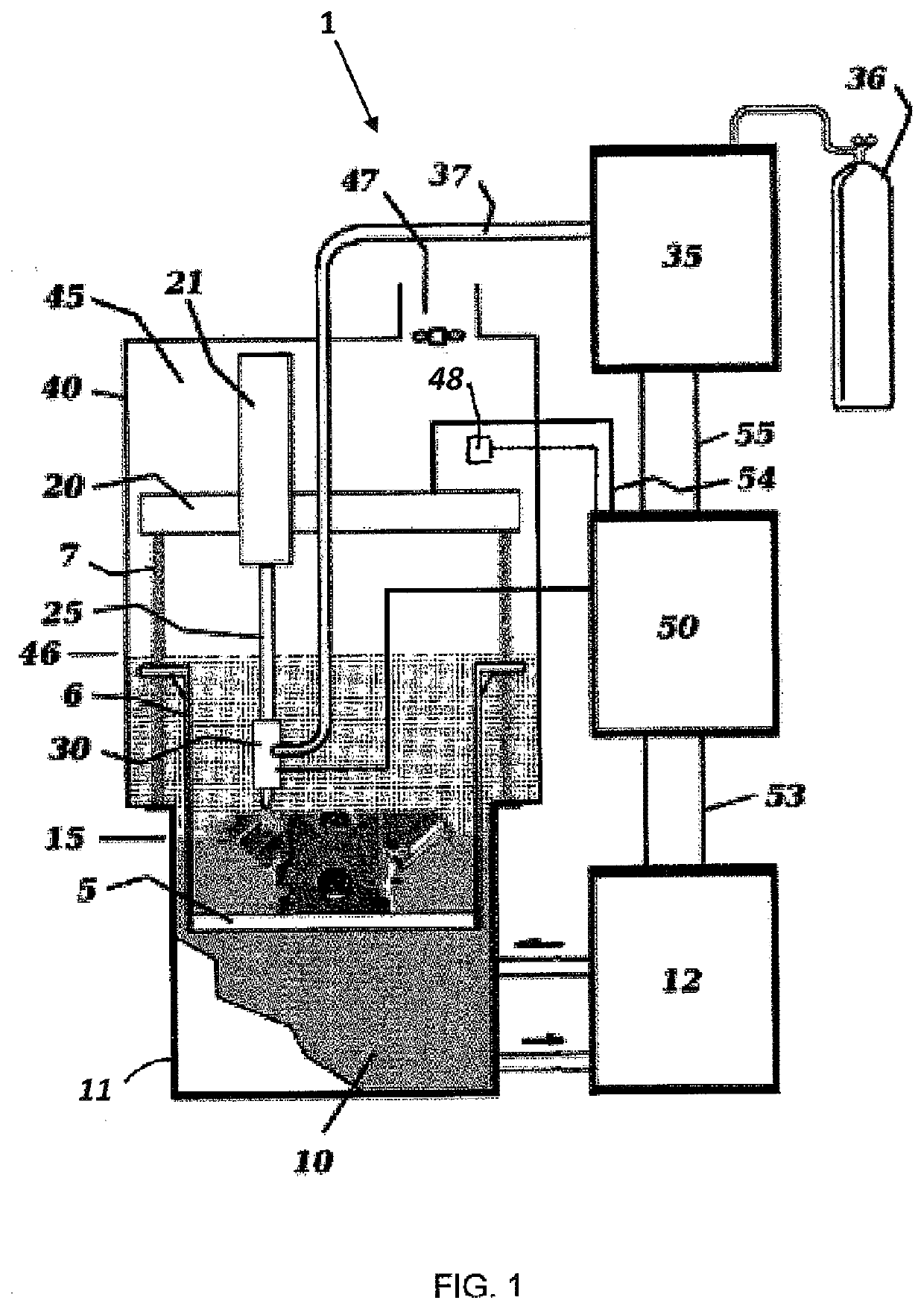
[0043]The present invention is directed to the fabrication of an object using three-dimensional computer models and computer numerical control (CNC) robotics to control the position of the application of a metal or metal-like deposit. The present invention is directed to form a metal-based or metallic two or three dimensional object, as contrasted with known three dimensional plastic printing technologies in use today for providing objects made of plastic. The fabrication of these objects formed of metal does not require the use expensive tooling or molds. Additionally, the present invention is particularly well suited to rapid prototyping and lower volume production of metallic parts.

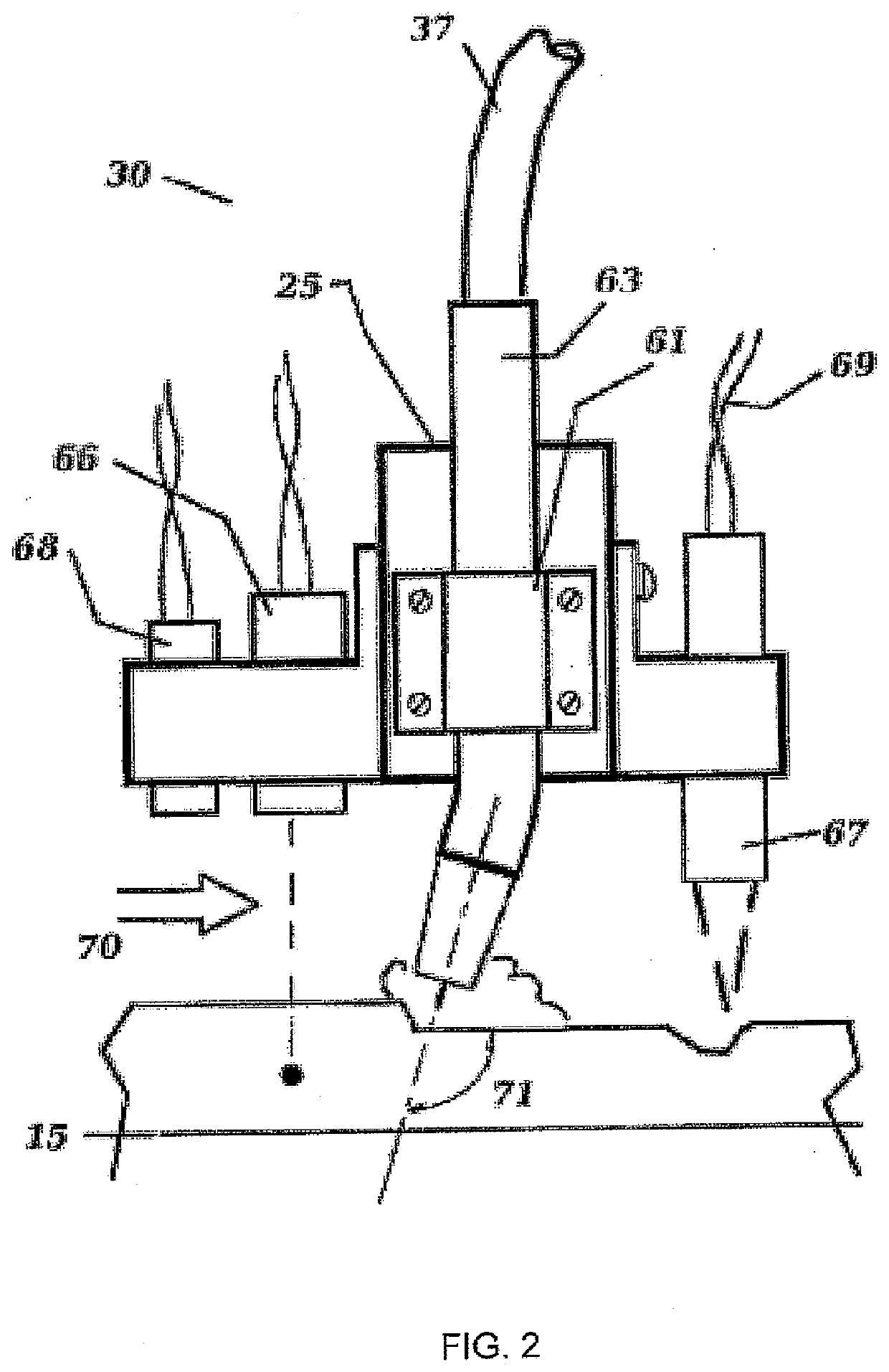
[0044]The preferred embodiment of the apparatus includes an inert gas arc nozzle fed with wire and gas, a non-stick build surface mounted to a moving table, a multi-axis robotic actuators, a master controller, sensors, a tank full of quenchant, an enclosure, and an air filtering system.

[0045]At least o...


PUM

PropertyMeasurementUnit
Temperatureaaaaaaaaaa

Abstract

A method and apparatus for depositing metals and metal-like substances in two and three dimensional form without a substrate in a safe, rapid and economical fashion using gas shielded arc welding equipment and programmable robotic motion. The method and apparatus includes the use and application of robotic controls, temperature and position feedback, single and multiple material feeds, and semi liquid deposition thereby creating near net shape parts particularly well suited to rapid prototyping and lower volume production. Anchor tabs applied as a first layer of deposited material and platen temperature control are provided to improve adherence and removal from the build surface.

Description

CROSS-REFERENCE TO RELATED APPLICATIONS[0001]This application is a CONTINUATION-IN-PART of U.S. patent application Ser. No. 14 / 518,121, filed Oct. 20, 2014 entitled “Method and Apparatus for Fabrication of Articles by Molten and Semi-molten Deposition” which claims the benefit of U.S. Provisional Patent Application Ser. No. 61 / 892,526 entitled “Method and Apparatus for Fabrication of Articles by Molten and Semi-molten Deposition”, filed Oct. 18, 2013, the disclosures of which are herein incorporated by reference in their entirety.FIELD OF THE INVENTION[0002]The present invention relates to equipment and processes used for the fabrication of parts by depositing layers of metallic material, commonly referred to as additive manufacturing, and more particularly to equipment and processes which fabricate metallic items formerly made by processes such as casting, welding, subtractive machining, and forging, and generally does so without the need for specialized tooling and long lead times...

Claims


Application Information

Patent Timeline
IPC IPC(8): B23K9/04B23K9/095B23K37/00B33Y10/00B33Y40/20
CPCB23K9/042B23K9/0953B33Y40/20B33Y10/00B23K37/003B23K9/04B23K9/167B23K9/173B23K9/0956B22F10/22B22F10/25
Inventor KRUER, THOMAS R.WESTERMEYER, AUBREY B.KRUER-ZERHUSEN, NATHAN J.
Owner MFG CO LTD
Learn More