Snubber Capacitor

a capacitor and snubber technology, applied in the direction of fixed capacitor details, stacked capacitors, printed circuit non-printed electric components association, etc., can solve the problems of large surge voltage and emi (electromagnetic interference) noise between drain and source terminals of power devices, limited smoothing effect of snubber capacitors, undesirable heat conduction efficiency, etc., to improve the thermal condition of snubber capacitors, enhance smoothing effect, and improve heat con

Pending Publication Date: 2022-06-23
ZF FRIEDRICHSHAFEN AG
View PDF1 Cites 0 Cited by
  • Summary
  • Abstract
  • Description
  • Claims
  • Application Information

AI Technical Summary

Benefits of technology

[0007]In order to improve the thermal condition of the snubber capacitor and enhance the smoothing effect, a snubber capacitor is disclosed. The snubber capacitor includes a first electrode, a second electrode and a capacitor core therebetween, a conductive first extraction element electrically coupled to the first electrode and covering at least a part of the first electrode and a part of the capacitor core, a conductive second extraction element electrically coupled to the second electrode and covering at least a part of the second electrode and another part of the capacitor core, wherein the first extraction element is electrically insulated from the second extraction element. With this design, the extraction elements enlarge the contact area between the snubber capacitor and elements coupled to the snubber capacitor (such as external connectors of an inverter, circuit patterns of a conductive layer of a power module). Thus, the heat dissipation of the snubber capacitor is improved.
[0010]According to another example aspect of the invention, the sidewall of the capacitor core covered by the first extraction element is adjacent to the sidewall of the capacitor core covered by the second extraction element. This snubber capacitor can be provided near the power elements of a power module to smooth the voltage surge and decrease the EMI noise.
[0012]According to another example aspect of the invention, at least one of the first extraction element and the second extraction element includes a base portion and two extended portions extending from the base portion along the longitudinal direction of the snubber capacitor, the two extended portions extending parallel to the two adjacent sidewalls of the capacitor core, respectively. In an alternative example embodiment, at least one of the first extraction element and the second extraction element includes a base portion and two extended portions extending from the base portion along the longitudinal direction of the snubber capacitor, the two extended portions extending parallel to the opposite sidewalls of the capacitor core, respectively. Snubber capacitors with adjacent extended portions are mainly used as inner snubber capacitors inside the power module, while snubber capacitors with opposite extended portions are used outside the power module. With these extraction elements, the heat-dissipating area of the snubber capacitor is increased, which improves the thermal effect of the snubber capacitor. Besides, the snubber capacitor is affected less by the stress change caused by temperature variations.

Problems solved by technology

In addition, the power devices are usually interfered with by stray inductance of a power module package and surrounding circuits, and fast switching capability of the power devices causes high voltage differentials over time (dv / dt), which results in large surge voltage and EMI (Electromagnetic Interference) noise between drain and source terminals of the power devices when switching off.
In the conventional inverter, the snubber capacitor is only provided adjacent to part of the power devices, thus the smoothing effect of the snubber capacitor is limited.
In this design, the heat generated by the MLCC 104 can only be dissipated through the solder material 6 which results in an undesirable heat conduction efficiency.
In some cases, the snubber capacitors are even burnt out under severe thermal conditions.

Method used


Image

  • Snubber Capacitor
  • Snubber Capacitor
  • Snubber Capacitor

Examples


Embodiment Construction

[0036]Reference will now be made to embodiments of the invention, one or more examples of which are shown in the drawings. Each embodiment is provided by way of explanation of the invention, and not as a limitation of the invention. For example, features illustrated or described as part of one embodiment can be combined with another embodiment to yield still another embodiment. It is intended that the present invention include these and other modifications and variations to the embodiments described herein.

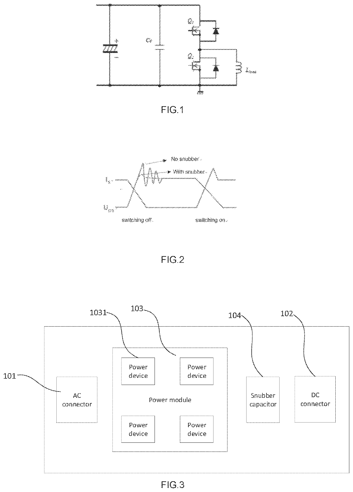
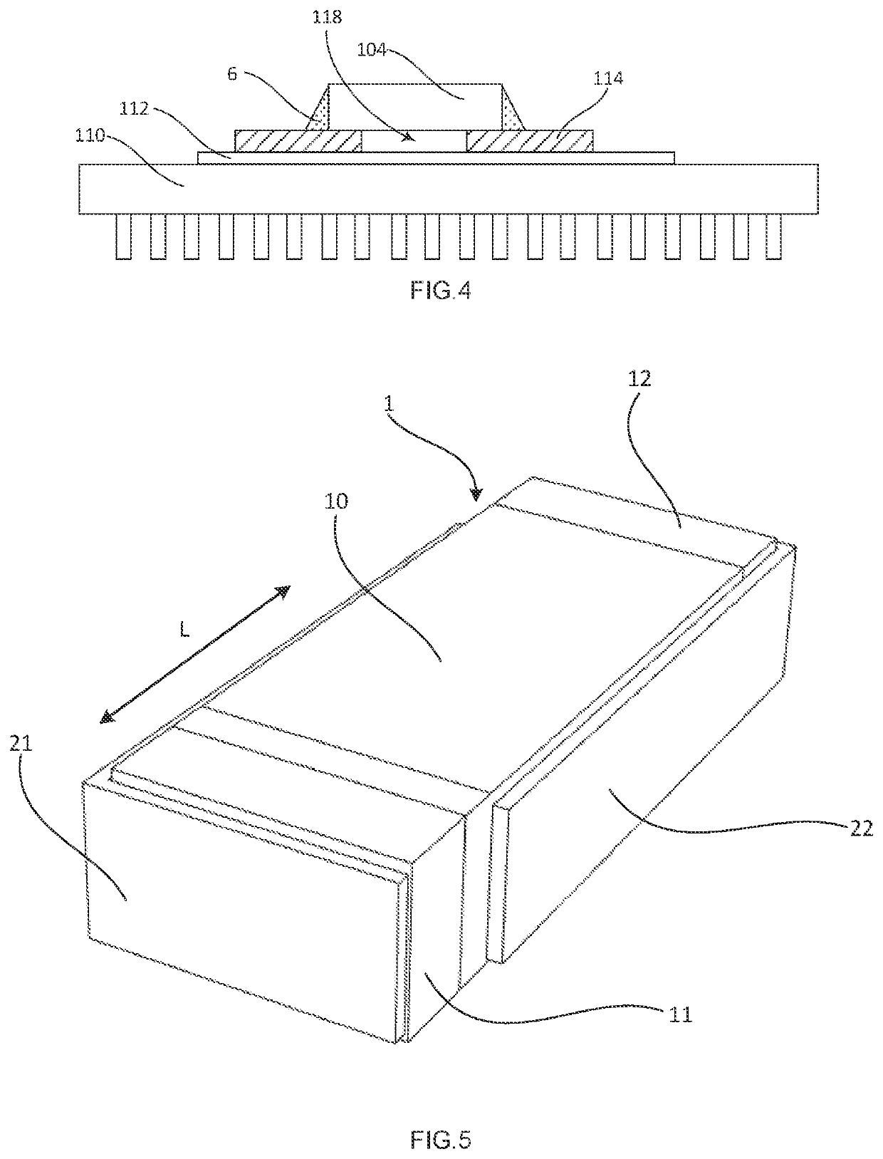
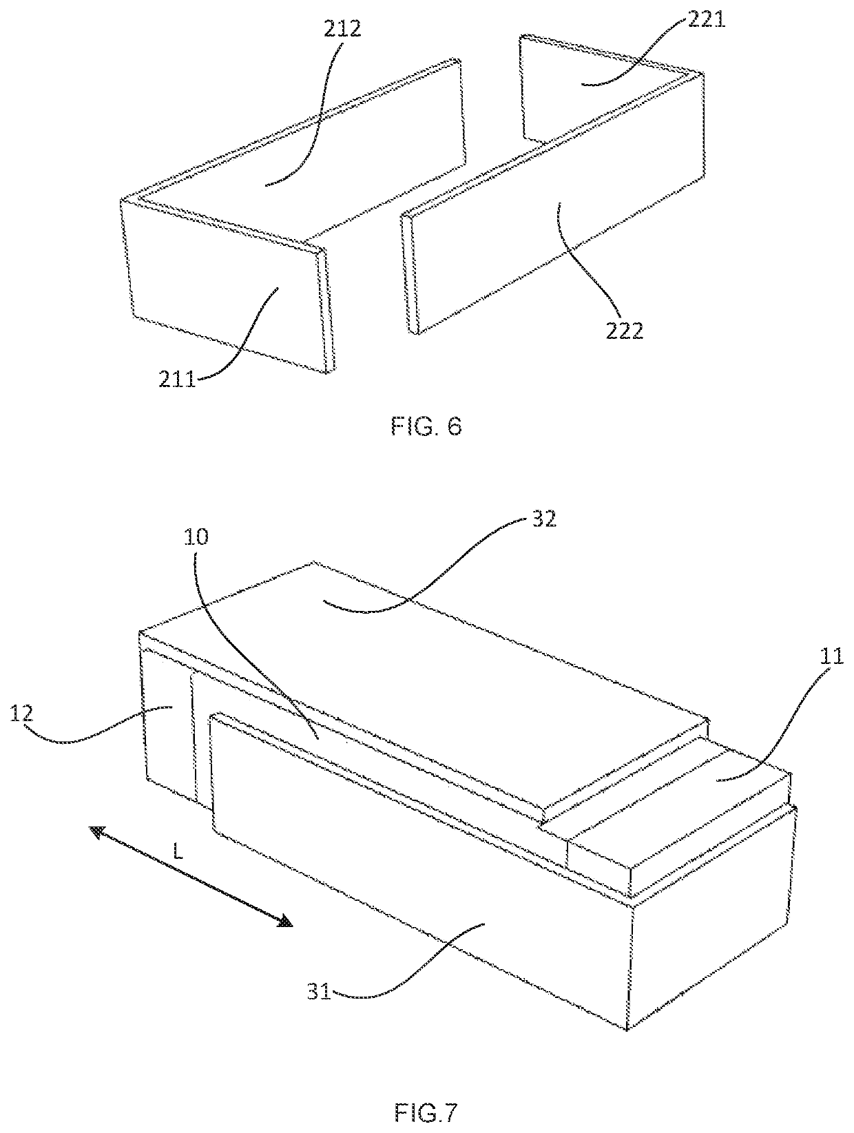
[0037]Referring now to the drawings, example embodiments of the invention are described in detailed. In this invention, the snubber capacitors of different embodiments are mainly used in Auto industry, such as in a power module of an inverter, or in an inverter of an electric vehicle. The snubber capacitors are provided inside a power module or adjacent to a power module. Unlike in PCB application, the operation conditions of the power modules are much stricter. For example, the o...


PUM

PropertyMeasurementUnit
operating temperatureaaaaaaaaaa

Abstract

A snubber capacitor includes a first electrode, a second electrode and a capacitor core therebetween. A conductive first extraction element is electrically coupled to the first electrode and covers at least a part of the first electrode and a part of the capacitor core. A conductive second extraction element is electrically coupled to the second electrode and covers at least a part of the second electrode and another part of the capacitor core. The first extraction element is insulated from the second extraction element.

Description

FIELD OF THE INVENTION[0001]The invention relates generally to a snubber capacitor, in particularly a snubber capacitor provided inside a power module.CROSS-REFERENCE TO RELATED APPLICATION[0002]The present application is related and has right of priority to German Patent Application No. 102020216473.8 filed in the German Patent Office on Dec. 22, 2020, which is incorporated by reference in its entirety for all purposes.BACKGROUND OF THE INVENTION[0003]Power devices (WBG (wide bandgap) semiconductors, such as SiC, GaN) are becoming more and more popular in applications where fast and efficient switching is required, such as power supply applications. In addition, the power devices are usually interfered with by stray inductance of a power module package and surrounding circuits, and fast switching capability of the power devices causes high voltage differentials over time (dv / dt), which results in large surge voltage and EMI (Electromagnetic Interference) noise between drain and sou...

Claims


Application Information

Patent Timeline
Patent Type & Authority Applications(United States)
IPC IPC(8): H02M1/34H02M7/00H05K1/02H05K1/18H01G4/30
CPCH02M1/34H02M7/003H05K2201/068H05K1/182H01G4/30H05K1/0271H01G4/228H01G4/232H01G2/08H01L25/16H02M1/346H01G2/06
Inventor LIU, WEI
Owner ZF FRIEDRICHSHAFEN AG
Why Eureka
Try Eureka