
Silicon-based anode material for lithium-ion battery, preparation method therefor, and battery

a lithium-ion battery and anode material technology, applied in the field of lithium-ion battery materials, can solve the problems of volume expansion and unstable interface reactions during the cycle, the theoretical specific capacity of 372 mah/g cannot meet people's increasing requirements for energy density, and the rapid decay of the cycle, etc., to achieve good rate performance, stable structure, and excellent cycle performance

Pending Publication Date: 2022-04-28
LIYANG TIANMU PILOT BATTERY MATERIAL TECH CO LTD
View PDF0 Cites 0 Cited by
  • Summary
  • Abstract
  • Description
  • Claims
  • Application Information

AI Technical Summary

Benefits of technology

The patent aims to provide a new type of material for the anode of lithium-ion batteries that overcomes the shortcomings of existing materials. The material is made of silicon coated with carbon nanotubes or carbon nanofibers, which results in a stable structure and improved cycle performance. The method of preparing this material is simple and efficient, and the resulting battery has high energy density, high cycle performance, and high-rate performance. In summary, the patent offers a promising solution to improve the performance of lithium-ion batteries.

Problems solved by technology

However, the theoretical specific capacity of 372 mAh / g can no longer meet people's increasing requirements for energy density, and the development of new anode materials has become a top priority.
It has basically become the consensus of the industry, but the problems of volume expansion and unstable interface reactions during the cycle have not been completely resolved.
However, it has been reported in the Reference (Effect of Volume Expansion on SEI Covering Carbon-Coated Nano-Si / SiO Composite Journal of The Electrochemical Society, 160 (10)) that the carbon film formed by ordinary coating will crack obviously during the charge and discharge cycle, resulting in the failure of the electrochemical contact of the material and the rapid decay of the cycle.
Therefore, it is a technical problem in the field of lithium-ion batteries to develop a silicon-based anode material with stable cycling and good conductivity.

Method used


Image

  • Silicon-based anode material for lithium-ion battery, preparation method therefor, and battery
  • Silicon-based anode material for lithium-ion battery, preparation method therefor, and battery
  • Silicon-based anode material for lithium-ion battery, preparation method therefor, and battery

Examples


embodiment 1

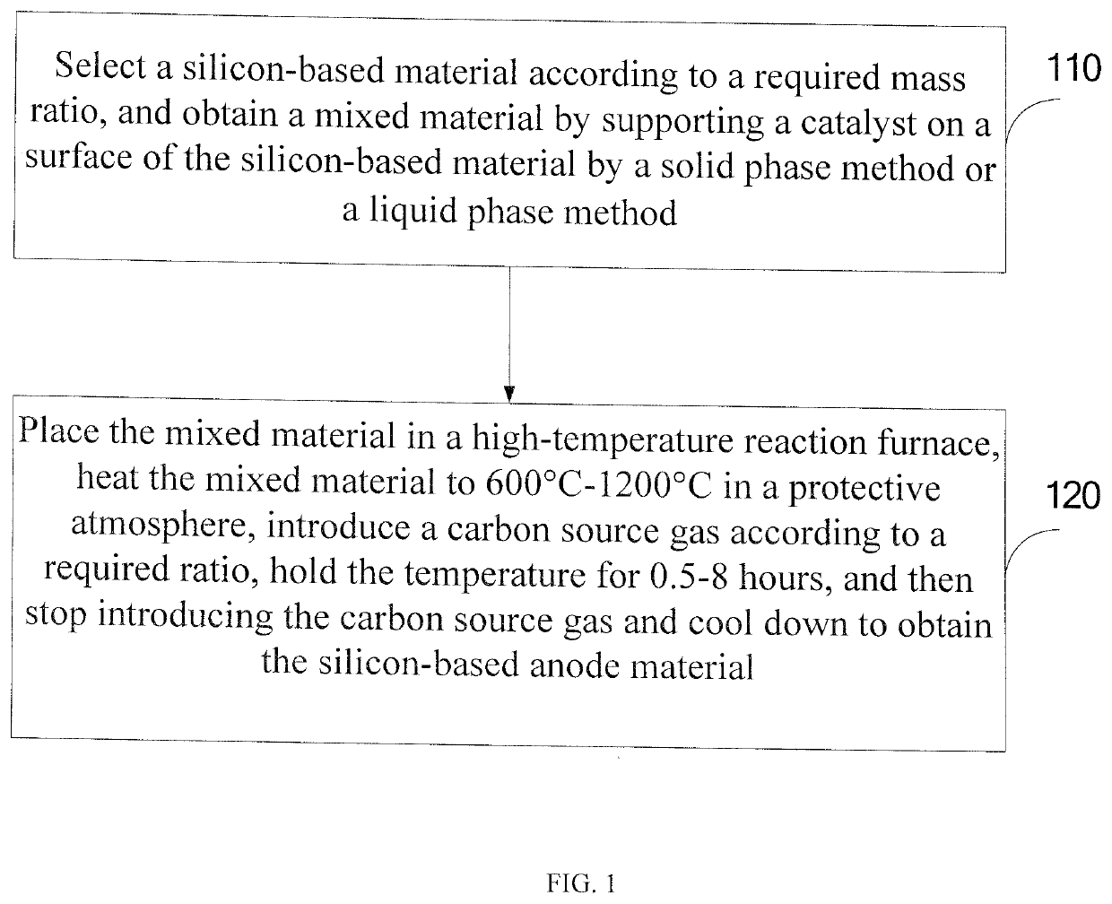
[0062]This embodiment provides a specific preparation method of a silicon-based anode material for a lithium-ion battery, including:

[0063]First, thoroughly mixing commercial product of Silicon monoxide powder with an aqueous solution of ferric chloride, and spray drying to obtain the catalyst-supported Silicon monoxide powder; wherein the weight fraction of ferric chloride is 0.05%; and

[0064]Second, placing the catalyst-supported Silicon monoxide powder in a high-temperature rotary furnace, heating the catalyst-supported Silicon monoxide powder to 900° C. under a mixed gas (Ar:H2=1:0.1), introducing acetylene gas of which the volume is equivalent to that of hydrogen, holding the temperature for 4 hours, then stopping introducing acetylene gas, and cooling down to obtain the Silicon monoxide composite material with carbon nanotubes grown in situ.

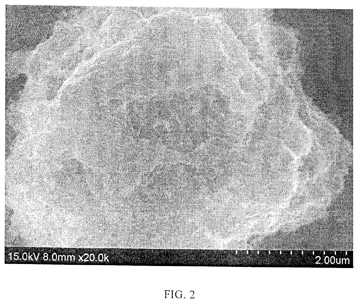
[0065]The SEM experiment of the disclosure was performed on an S-4800 scanning electron microscope, and the same operation was applied to th...

embodiment 2

[0072]This embodiment provides a specific preparation method of a silicon-based anode material, including:

[0073]First, thoroughly mixing commercial product of Silicon monoxide powder with nano iron oxide in a high-speed VC machine, thus obtaining a catalyst-supported Silicon monoxide powder; wherein the weight fraction of nano iron oxide is 0.05%; and

[0074]Second, placing the catalyst-supported Silicon monoxide powder in a high-temperature rotary furnace, heating the catalyst-supported Silicon monoxide powder to 900° C. under a mixed gas (Ar:H2=1:0.1), introducing acetylene gas of which the volume is equivalent to that of hydrogen, holding the temperature for 4 hours, then stopping introducing acetylene gas, and cooling down to obtain the Silicon monoxide composite material with carbon nanotubes grown in situ.

[0075]The Raman spectrum of the material obtained in this embodiment is shown in FIG. 7. It can be seen from FIG. 7 that there is a bulge of amorphous silicon at 475 cm−1;

[0076...

embodiment 3

[0078]This embodiment provides a specific preparation method of a silicon-based anode material, including:

[0079]First, thoroughly mixing commercial product of Silicon monoxide powder with nano metallic copper in a high-speed VC machine, thus obtaining a catalyst-supported Silicon monoxide powder; wherein the weight fraction of nano metallic copper is 0.05%; and

[0080]Second, placing the catalyst-supported Silicon monoxide powder in a high-temperature rotary furnace, heating the catalyst-supported Silicon monoxide powder to 1000° C. under a mixed gas (Ar:H2=1:0.1), introducing methane gas of which the volume is equivalent to that of hydrogen, holding the temperature for 4 hours, then stopping introducing methane gas, and cooling down to obtain the Silicon monoxide composite material with carbon nanotubes grown in situ.

[0081]The SEM image of the Silicon monoxide composite material with carbon nanotubes grown in situ obtained in this example is shown in FIG. 9. It can be seen from that ...


PUM

PropertyMeasurementUnit
Temperatureaaaaaaaaaa
Timeaaaaaaaaaa
Angleaaaaaaaaaa

Abstract

The invention relates to a silicon-based anode material for a lithium-ion battery, a preparation method therefor, and a battery. The silicon-based negative electrode material is prepared by the compounding of 90 wt %-99.9 wt % of a silicon-based material and 0.1 wt %-10 wt % of carbon nanotubes and / or carbon nanofibers which grow on the surface of the silicon-based material in situ.

Description

[0001]The present disclosure claims the priority to a Chinese Patent Disclosure No. 201810978803.2, entitled “Silicon-based Anode Material for Lithium-ion Battery, Preparation Method Therefor, and Battery,” filed in the China National Intellectual Property Administration on Aug. 27, 2018, as well as PCT Application No. PCT / CN2019 / 077119 filed Mar. 6, 2019.BACKGROUND OF THE INVENTIONTechnical Field[0002]The disclosure relates to the technical field of lithium battery materials, and in particular to a silicon-based anode material for a lithium-ion battery, a preparation method therefor, and a battery.Description of Related Art[0003]Since its first appearance in the 1990s, lithium-ion batteries have gradually occupied the portable consumer electronics market represented by mobile phones and computers. They also have broad disclosure prospects in the field of large-scale energy storage and electric vehicles. Lithium-ion battery anode materials have gradually evolved from coke-based mate...

Claims


Application Information

Patent Timeline
IPC IPC(8): H01M4/62B01J21/06H01M4/48B01J27/25B01J27/125B01J27/128B01J23/72B01J23/755B01J23/745C01B32/162B01J35/02H01M4/38H01M4/36H01M10/0525C01B32/159B01J37/02B01J37/08H01M4/02
CPCH01M4/625H01M2004/021H01M4/483B01J27/25B01J27/125B01J27/128B01J23/72B01J23/755B01J23/745C01B32/162B01J35/023H01M4/386H01M4/364H01M10/0525C01B32/159B01J37/0236B01J37/08C01B2202/06C01P2002/82C01B2202/36C01B2202/02C01P2002/72C01B2202/34H01M2004/027C01B2202/22B01J21/06H01M4/366H01M4/38H01M4/485B82Y30/00Y02E60/10H01M4/131H01M4/1391H01M10/052D06M11/74C01B33/113B82Y40/00B01J35/40
Inventor LUO, FEILIU, BONANCHU, GENGLU, HAO
Owner LIYANG TIANMU PILOT BATTERY MATERIAL TECH CO LTD
Learn More