
Quantum-limited Extreme Ultraviolet Coherent Diffraction Imaging

a coherent diffraction and quantum-limited technology, applied in the field of quantum-limited extended ultraviolet (including xray) coherent diffraction imaging, can solve the problems of large impact of cdi techniques, severe limitation of imaging resolution, and often critical limitation of dose on the sample, and achieve the effect of improving accuracy

Pending Publication Date: 2022-03-31
UNIV OF COLORADO THE REGENTS OF
View PDF0 Cites 2 Cited by
  • Summary
  • Abstract
  • Description
  • Claims
  • Application Information

AI Technical Summary

Benefits of technology

The present invention provides apparatus and methods for coherent diffraction imaging in the extended ultraviolet to soft x-ray range. This is accomplished using a CMOS or similar detector and by collecting raw data, measuring diffraction patterns from the object, and generating raw CDI data. The raw CDI data is then preprocessed and reconstructed into an image of the object using an algorithm such as Poisson denoising. The invention also allows for scanning the illumination or object to collect diffraction patterns and collecting many frames of data at each stopping point for better accuracy.

Problems solved by technology

CDI techniques have had an outsize impact on extended-ultraviolet (EUV) and x-ray imaging, because prior to CDI, imaging resolution was severely limited by limitations in the imaging optics, which were only capable of ˜5-10× the diffraction limit.
Again, for x-ray imaging, dose on the sample is often a critical limitation, particularly for imaging of living systems.
However, one serious limitation of CDI techniques is the limited readout rate of the EUV sensitive charge-coupled device (CCD) detectors.
Furthermore, since exposure times to saturate the detector are often <<1 sec, imaging is slow and most of the photon flux from the source is wasted—since the beam is blocked during imager readout.
The remaining disadvantage of the CMOS detector—fixed pattern noise due to fluctuations in amplifier gain—has been mitigated by routine pixel-by-pixel calibration and background subtraction.
Unfortunately, CMOS technology has not yet been commercialized for imaging in the deep-ultraviolet to x-ray regions of the spectrum.
Using CMOS imaging detectors to detect photons in the EUV spectral range, however, does not present any unique challenges—it is technically feasible and simply requires an appropriate imager design.

Method used


Image

  • Quantum-limited Extreme Ultraviolet Coherent Diffraction Imaging
  • Quantum-limited Extreme Ultraviolet Coherent Diffraction Imaging
  • Quantum-limited Extreme Ultraviolet Coherent Diffraction Imaging

Examples


Embodiment Construction

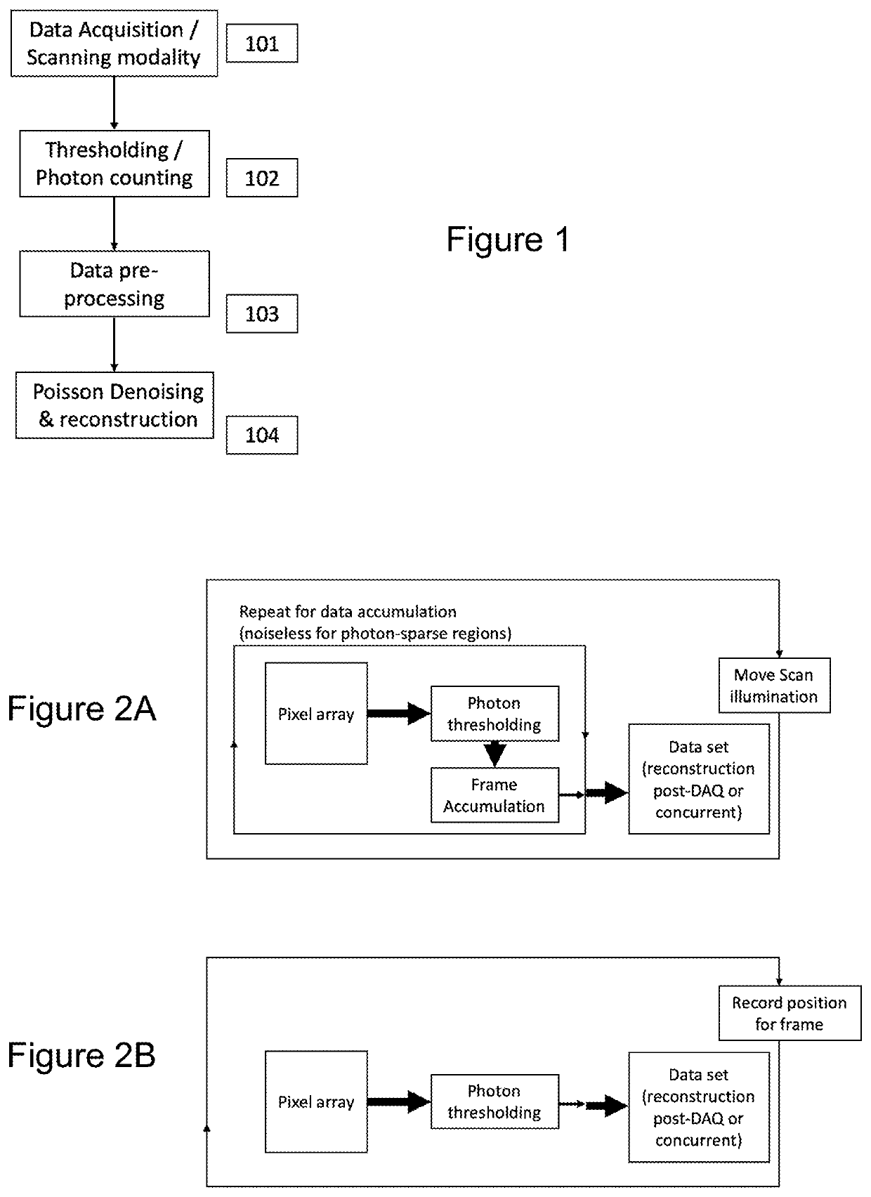
[0023]FIG. 1 is a flow diagram showing the overall process of quantum-limited extended ultraviolet coherent diffraction imaging according to the present invention. In step 101 data is acquired in a CDI configuration (see FIGS. 2A-D). In step 102, detector pixels are thresholded (see FIG. 3). In step 103, data preprocessing is performed (see FIG. 4). In step 104, the image is reconstructed. FIGS. 6-9 illustrate examples of data acquisition apparatus. Extended ultraviolet range has a wavelength of about 10 nm-200 nm or 10 nm-250 nm, while soft x-ray has a wavelength of about 1 nm-10 nm. Extended ultraviolet range includes extreme UV, generally defined as 10 nm-100 nm.

[0024]Various modalities of scanning and data acquisition may be performed in step 101. See FIGS. 2A-2D for examples of scanning and data acquisition modalities.

[0025]Thresholding of detector 615 pixels is performed in step 102. FIG. 3 illustrates an example of this process. A typical use of EUV imaging would be to detect...


PUM


Abstract

Apparatus and methods for coherent diffraction imaging This is accomplished by acquiring data in a CDI setup with a CMOS or similar detector. The object is illuminated with coherent light such as EUV light which may be pulsed. This generates diffraction patterns which are collected by the detector, either in frames or continuously (by recording the scan position during collection). Pixels in the CDI data are thresholded and set to zero photons if the pixel is below the threshold level. Pixels above the threshold may be set to a value indicating one photon, or multiple thresholds may be used to set pixels values to one photon, two photons, etc. In addition, multiple threshold values may be used to detect different photon energies for illumination at multiple wavelengths.

Description

BACKGROUND OF THE INVENTIONField of the Invention[0001]The present invention relates to coherent diffraction imaging. In particular, the present invention relates to quantum-limited extended ultraviolet (including x-ray) coherent diffraction imaging.Discussion of Related Art[0002]Recent work demonstrating imaging using coherent light at 13.5 nm wavelength has yielded the highest-resolution full-field optical imaging as-yet demonstrated in a tabletop-scale setup. A resolution of 12.6 nm has been achieved using Coherent Diffractive Imaging (CDI), which directly detects the light scattered from an object without the use of an imaging optics, then reconstructs an image computationally. CDI techniques have had an outsize impact on extended-ultraviolet (EUV) and x-ray imaging, because prior to CDI, imaging resolution was severely limited by limitations in the imaging optics, which were only capable of ˜5-10× the diffraction limit.[0003]By eliminating all optics between the object and the ...

Claims


Application Information

Patent Timeline
IPC IPC(8): G03F7/20G01N23/20
CPCG03F7/2039G01N2223/1006G01N23/20G03F7/70616G03F1/84G01N23/20008G01N23/20091G01N23/2055G01N23/205
Inventor KAPTEYN, HENRY C.WANG, BINLIAO, CHEN-TINGMURNANE, MARGARET
Owner UNIV OF COLORADO THE REGENTS OF
Learn More