Semiconductor memory device including latency setting circuit
- Summary
- Abstract
- Description
- Claims
- Application Information
AI Technical Summary
Benefits of technology
Problems solved by technology
Method used
Image
Examples
first embodiment
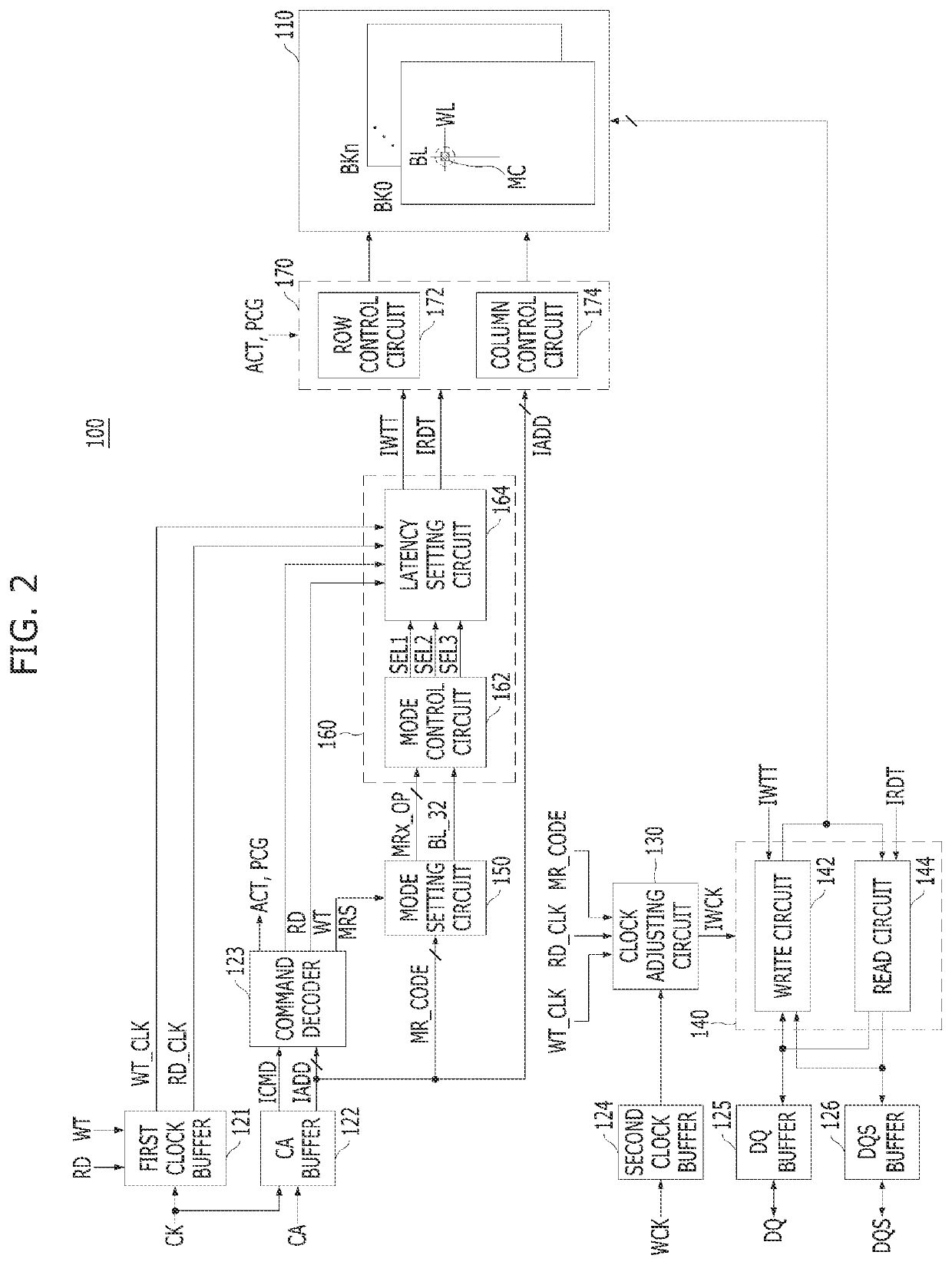
[0079]FIG. 6 is a detailed circuit diagram illustrating the latency setting circuit 164 according to the present invention.
[0080]Referring to FIG. 6, the latency setting circuit 164 may include a write latency circuit 210 and a read latency circuit 230.
[0081]The write latency circuit 210 may include a preliminary latency circuit 212 and a main latency circuit 214. The preliminary latency circuit 212 may generate a preliminary write command WTT by delaying the write command WT by a first latency according to the write clock WT_CLK. In this case, the first latency is a delay time defined in the process from the input of the write command to the actual input of the write data and may correspond to ‘write latency WL+burst length BL / width (N) of one data item+1’. The main latency circuit 214 may set a second latency according to the first to third mode selection signals SEL1 to SEL3 and generate the internal write command IWTT by further delaying the preliminary write command WTT by the ...
second embodiment
[0086]FIG. 7 is a detailed circuit diagram illustrating the latency setting circuit 164 according to the present invention. FIG. 8 is a circuit diagram illustrating a control signal generating circuit 312 as illustrated in FIG. 7. FIG. 9 is a circuit diagram illustrating an interval defining circuit 314 as illustrated in FIG. 7. FIG. 10 is a circuit diagram illustrating a clock driver 316 as illustrated in FIG. 7.
[0087]Referring to FIG. 7, the latency setting circuit 164 may include a clock driving circuit 310, a write latency circuit 320, and a read latency circuit 330.
[0088]During a write operation, the clock driving circuit 310 may delay the write clock WT_CLK by the latency corresponding to the activated mode selection signal among the first to third mode selection signals SEL1 to SEL3 to thereby generate a write trigger signal WTCLK_BL32. During a read operation, the clock driving circuit 310 may delay the read clock RD_CLK by the latency corresponding to the activated mode sel...
third embodiment
[0117]Since two write commands WT are input in the bank group mode, the timing margin may not be sufficient as compared with that in the individual bank mode. A method for further securing a timing margin in the bank group mode is described below according to the present invention.
[0118]FIG. 13 is a detailed circuit diagram illustrating the latency setting circuit 164 according to a third embodiment of the present invention. FIG. 14 is a circuit diagram illustrating an interval defining circuit 514 as illustrated in FIG. 13. FIG. 15 is a circuit diagram illustrating a clock driver 516 as illustrated in FIG. 13.
[0119]Referring to FIG. 13, the latency setting circuit 164 may include a clock driving circuit 510, a write latency circuit 520, and a read latency circuit 530. The write latency circuit 520 and read latency circuit 530 of FIG. 13 are substantially the same in circuit configuration as the write latency circuit 320 and the read latency circuit 330 of FIG. 7, respectively.
[0120...
PUM
 Abstract
Description
Claims
Application Information
 - R&D
- Intellectual Property
- Life Sciences
- Materials
- Tech Scout
- Unparalleled Data Quality
- Higher Quality Content
- 60% Fewer Hallucinations
Browse by: Latest US Patents, China's latest patents, Technical Efficacy Thesaurus, Application Domain, Technology Topic, Popular Technical Reports.
© 2025 PatSnap. All rights reserved.Legal|Privacy policy|Modern Slavery Act Transparency Statement|Sitemap|About US| Contact US: help@patsnap.com


