
Method for manufacturing a porous abradable coating made of ceramic material

Pending Publication Date: 2021-11-04
SN DETUDE & DE CONSTR DE MOTEURS DAVIATION S N E C M A
View PDF0 Cites 0 Cited by
  • Summary
  • Abstract
  • Description
  • Claims
  • Application Information

AI Technical Summary

Benefits of technology

This patent describes a ceramic material that has tiny holes and can be easily scratched by rubbing it with a part that will get little damage. This allows for improved energy efficiency in turbomachines, as the smooth layer doesn't significantly affect the mechanical properties of the material.

Problems solved by technology

On the other hand, their use is rarer in the turbines of such turbomachines, and especially in high-pressure turbines in which extreme physicochemical and thermal conditions prevail.
Indeed, the exhaust gases from the combustion chamber enter the high-pressure turbine at very high temperature and pressure levels, which leads to premature wear of the conventional abradable tracks.
However, it is naturally understood that, in such a case, the integrity of the blades is no longer ensured in case of contact with the stator, which necessitates the provision of a larger clearance between the rotor and the stator and therefore increases the leakage rate at the top of the blades and thus reduces the performance of the turbine.
Furthermore, due to the point friction with the blades and the heat of the exhaust gases, the coating may be damaged and provide less protection for the stator.
A disadvantage of these coatings is that aluminum is susceptible to self-ignition, and thus deflagration, phenomena during compressor operation.
These phenomena may lead to accelerated wear of the abradable coating and the surrounding parts in the turbomachine.
In order to reduce the risk of deflagration, the turbomachine comprises a relatively complex cooling system, which increases the production costs and / or makes the assembly of such a turbomachine relatively complex.
However, the total porosity of such coatings is generally limited to about 30% by volume, which limits their ability to be eroded by the rotor blades.
These plates are not obtained by thermal spraying and their porosity is relatively low.
There is thus a need for abradable turbomachine coatings that are non-explosive and have relatively high porosity, these coatings not being obtained by thermal spraying.

Method used


Image

  • Method for manufacturing a porous abradable coating made of ceramic material
  • Method for manufacturing a porous abradable coating made of ceramic material
  • Method for manufacturing a porous abradable coating made of ceramic material

Examples


Embodiment Construction

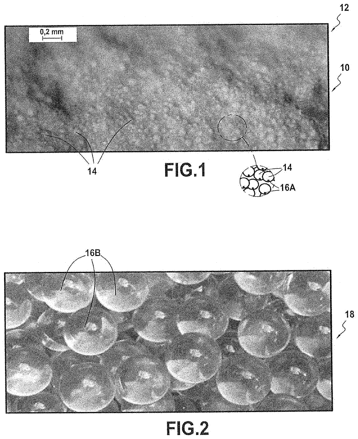
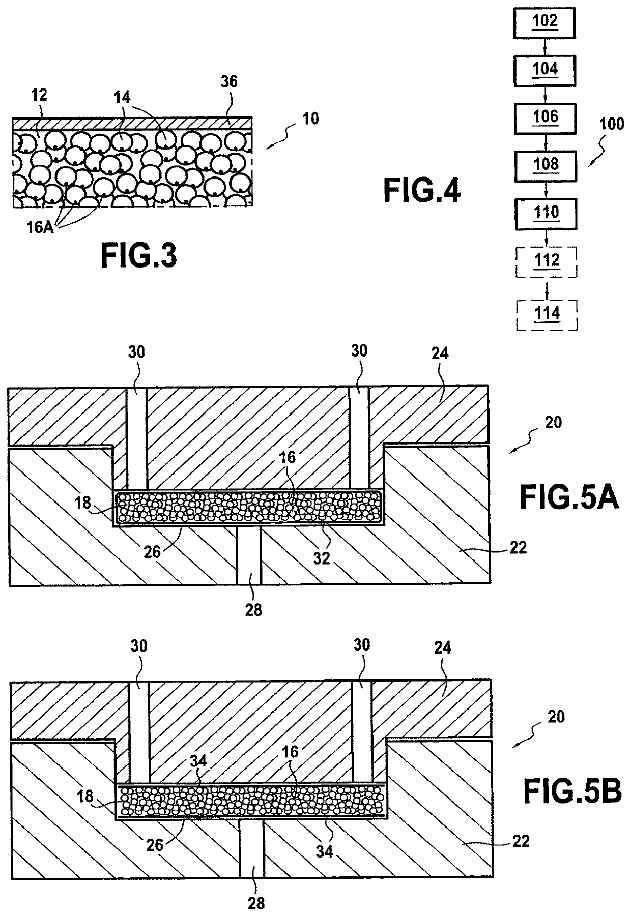
[0074]FIG. 1 is a view of a fracture face of a porous abradable ceramic coating 10. The porous abradable coating 10 includes a ceramic layer 12 having pores 14. As shown schematically in the enlargement of FIG. 1, the pores 14 of the layer 12 include glass 16A.

[0075]This glass 16A is present in the pores 14 of the ceramic layer 12 and results from the manufacturing process of the porous abradable coating 10. This glass 16A may be identified, for example, during analysis by X-ray fluorescence (XRF) spectroscopy. This technique makes it possible to identify elements present in the glass 16A that are not present in the ceramic material. The presence of the glass 16A may thus be identified.

[0076]This glass 16A comes from hollow glass beads 16B that are used to create porosity in the porous abradable coating 10. Hollow glass beads 16B that may be used in the manufacturing process of the porous abradable coating 10 are represented in FIG. 2.

[0077]The hollow glass beads 16B may be borosili...


PUM

PropertyMeasurementUnit
Percent by volumeaaaaaaaaaa

Abstract

A process for manufacturing a porous abradable coating includes: filling a mold with hollow glass or thermosetting polymer beads and a slurry; and sintering heat treatment to obtain a ceramic layer with pores. A maximum sintering temperature of the green body of the ceramic part is either higher than the melting temperature of the hollow glass beads so that at the end of the sintering heat treatment the hollow glass beads are melted, or higher than the decomposition temperature of the hollow thermosetting polymer beads so that at the end of the sintering heat treatment the hollow thermosetting polymer beads are decomposed.

Description

BACKGROUND OF THE INVENTION[0001]The present disclosure relates to a porous ceramic coating, in particular an abradable coating for a turbomachine part, and its manufacturing process.[0002]Many parts of turbomachines, as well as parts of turbojet nozzles, are today provided with coatings. “Coating” refers to a substantially continuous layer of material, this layer being interposed between the part it covers and the fluid flowing through the turbomachine or nozzle. A coating may comprise a different material than the material of the part it covers. A coating may also be divided into several sub-elements that, together, cover the part.[0003]In many rotating machines, it is now known to provide the stator ring with abradable tracks opposite the top of the rotor blades. Such tracks are made using so-called “abradable” materials which, when they come into contact with the rotating blades, wear more easily than the latter. This ensures a minimum clearance between the rotor and the stator,...

Claims


Application Information

Patent Timeline
IPC IPC(8): C04B41/45C04B41/50
CPCC04B41/4505C04B41/4582C04B41/5027C04B35/01C04B35/10C04B35/62222C04B35/62675C04B35/6268C04B38/008C04B2111/00362C04B2111/00982C04B2111/40C04B2235/3217C04B2235/6028C04B2235/606F01D11/122C04B38/061C04B38/067
Inventor LE BIEZ, PHILIPPE CHARLES ALAINDROZ, NICOLASLIAIS, LUDOVIC PHILIPPESELEZNEFF, SERGE GEORGES VLADIMIR
Owner SN DETUDE & DE CONSTR DE MOTEURS DAVIATION S N E C M A
Learn More