Ladle shroud for liquid metal casting installation

Active Publication Date: 2015-11-03
VESUVIUS GRP SA
View PDF17 Cites 0 Cited by
  • Summary
  • Abstract
  • Description
  • Claims
  • Application Information

AI Technical Summary

Benefits of technology

The invention is a new type of shroud that is stronger and more durable than previous versions. It can withstand more loadings, especially tensile stress, which is likely to occur at the end of the shroud when it is introduced into the installation. The shroud has attachment means to tube driving means, which allows it to be moved and held in the casting installation. Additionally, the mechanical properties of the shroud are sufficient, so a frame is not needed. The method for manufacturing the shroud is simple and cost-effective.

Problems solved by technology

This operation is in fact often made very difficult by the droplets of set steel which have been splashed during the casting operations.

Method used


Image

  • Ladle shroud for liquid metal casting installation
  • Ladle shroud for liquid metal casting installation

Examples


Embodiment Construction

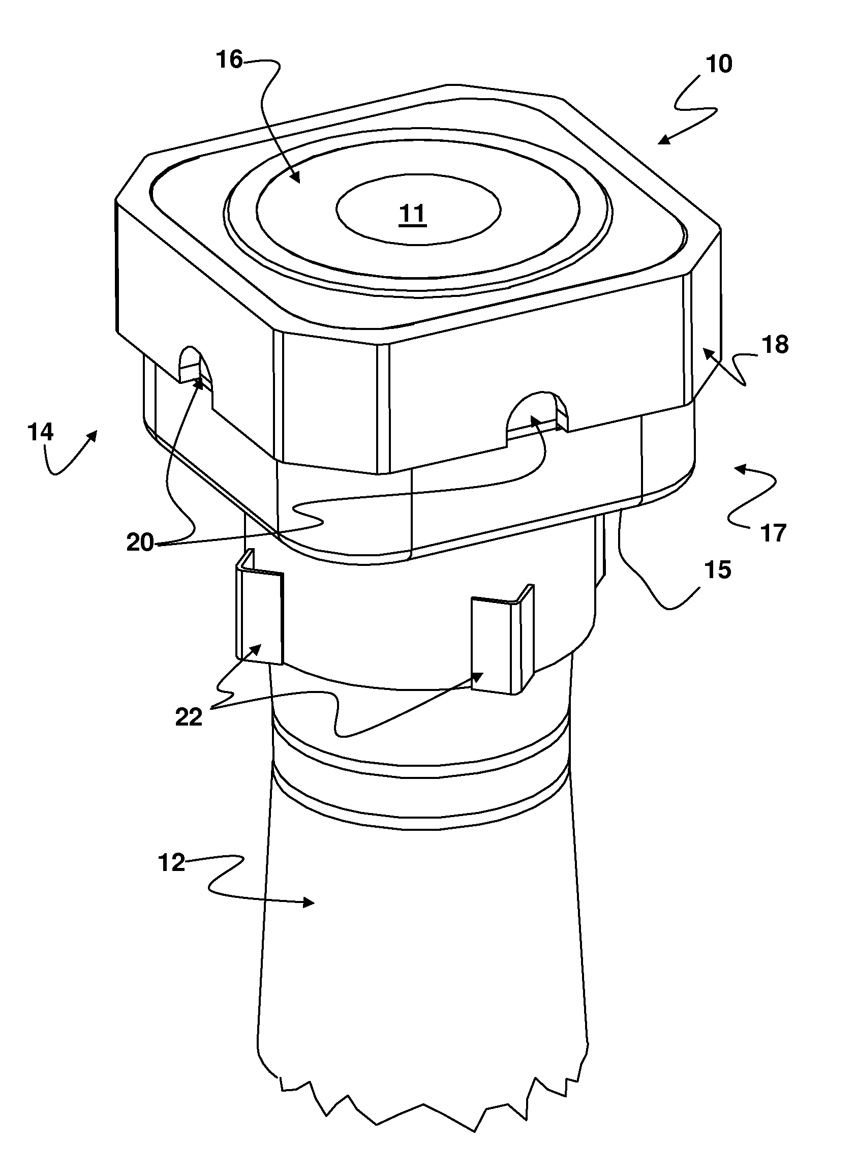
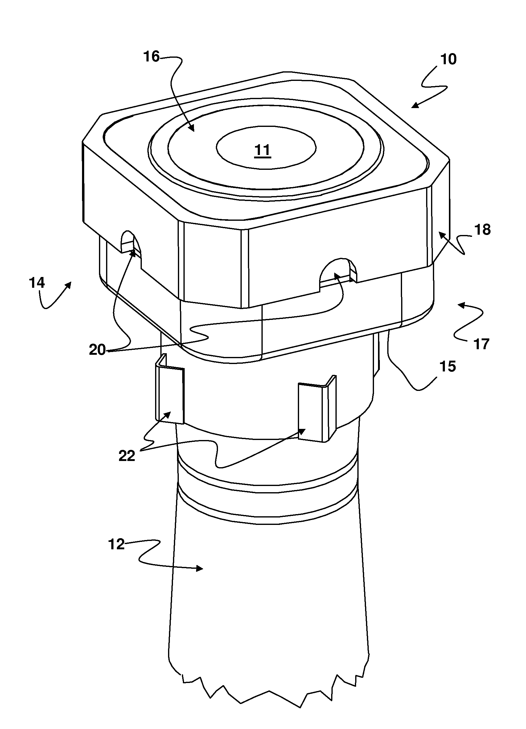
[0029]The FIGURE depicts a ladle shroud 10 for a liquid metal, notably liquid steel, casting installation. The shroud 10 comprises a canal 11 along which the metal can pass, extending essentially along an axis, the axis being vertical when the shroud is in the position of use. The FIGURE notably depicts an upper end of the shroud when this shroud is in its position of use, that is to say an end able to be in contact with an upstream element of the casting installation.

[0030]The shroud comprises a tube body 12 made of a refractive material and, at its end, a head 14 of square cross section with a shape distinct from a cross section of the tube body 12, which is of circular cross section. The cross section is defined as being normal to the axis of the canal 11.

[0031]Further, the square cross section of the head 14 is larger in size than the circular cross section of the tube body 12 and, as a result, between the head 14 and the body 12 of the shroud, the ladle shroud 10 comprises a re...


PUM

PropertyMeasurementUnit
Thicknessaaaaaaaaaa
Thicknessaaaaaaaaaa
Sizeaaaaaaaaaa

Abstract

A ladle shroud for casting liquid metal contains a canal along which the metal can pass, extending essentially along an axis, and a metallic jacket positioned at an end portion of the shroud that corresponds to an end of the canal, characterized in that the jacket comprises at least a belt of a thickness greater than or equal to 10 mm, preferably of 14 mm, and in that the shroud comprises means of attachment to driving means, the attachment means being formed on the jacket, notably on the belt thereof.

Description

BACKGROUND OF THE INVENTION[0001](1) Field of the Invention[0002]The present invention relates to a casting installation for liquid metal and notably to a ladle shroud that can be introduced into such an installation.[0003](2) Description of the Related Art[0004]A ladle shroud is a tube comprising a canal extending essentially along an axis; the canal allowing the liquid metal from a metallurgical container, such as a ladle, to pass to a tundish. Such a tube is introduced into the installation in such a way that the axis of the canal is vertical and that the upper end thereof is in contact with an upstream element of the installation, while the lower end thereof is immersed in the tundish.[0005]A ladle shroud comprising, at an end portion of the shroud corresponding to an upper end portion of the canal, a metallic jacket framing a tube body is known from the prior art and this metallic jacket is of a thickness less than or equal to 5 millimeters. Such a jacket, because of its small ...

Claims


Application Information

Patent Timeline
IPC IPC(8): B22D41/00B22D41/50B22D11/106
CPCB22D41/50B22D11/106B22D11/04B22D11/10B22D41/22B22D41/24B22D41/44B22D41/56
Inventor COLLURA, MARIANO
Owner VESUVIUS GRP SA
Why Eureka
Try Eureka