
Apparatus and method for fast volumetric fluorescence microscopy using temporally multiplexed light sheets

Active Publication Date: 2021-10-21
THE UNIVERSITY OF HONG KONG
View PDF1 Cites 1 Cited by
  • Summary
  • Abstract
  • Description
  • Claims
  • Application Information

AI Technical Summary

Benefits of technology

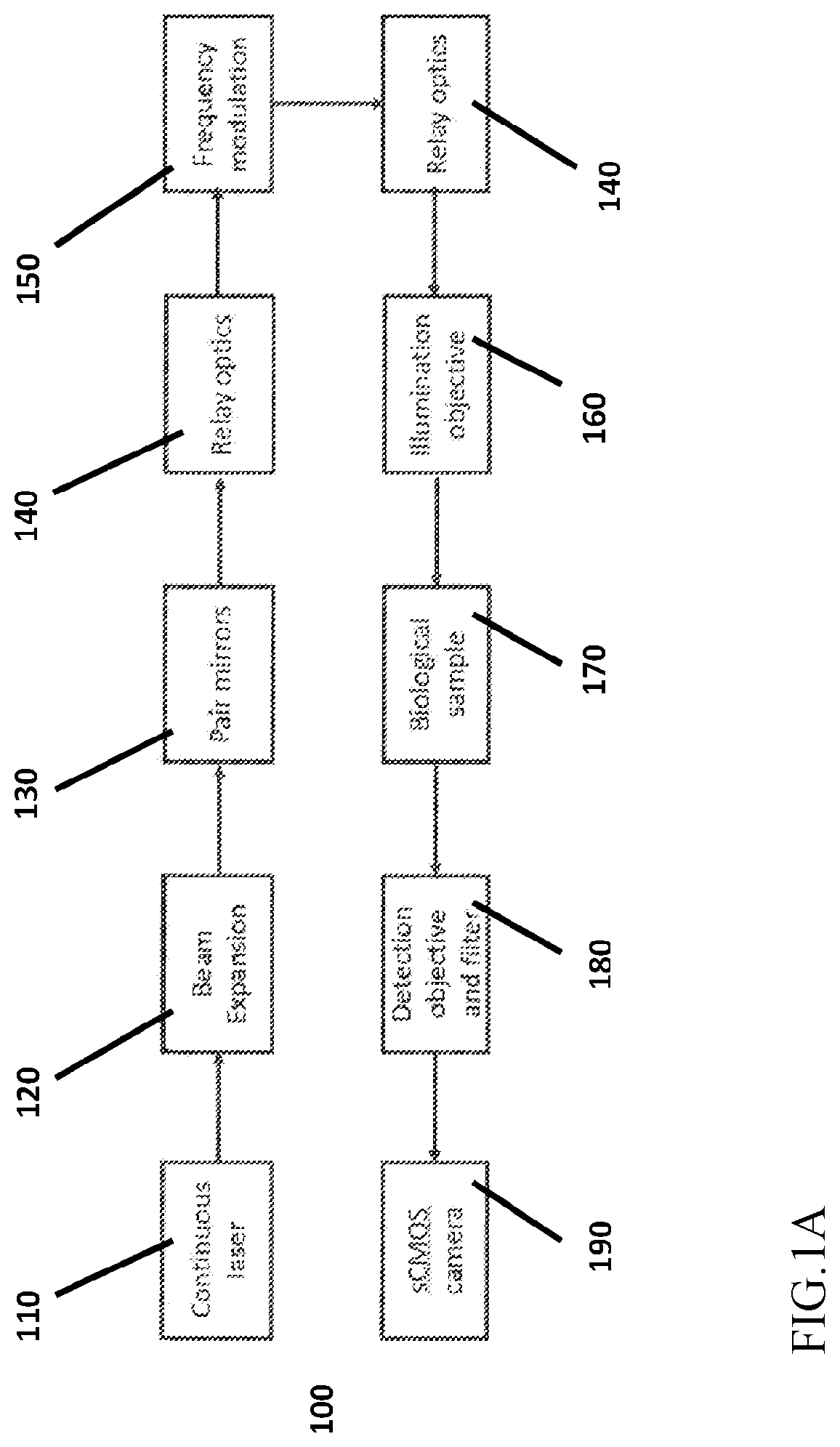
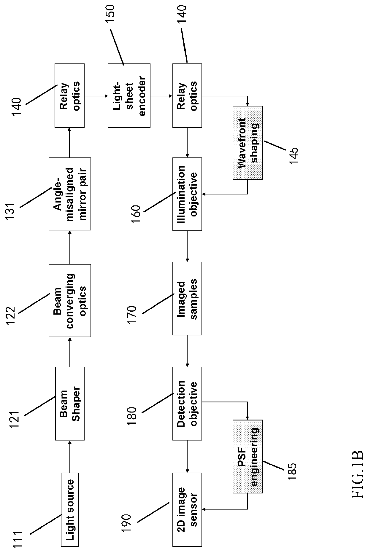
The patent describes a new approach to fluorescence microscopy called coded light-sheet array microscopy (CLAM) that allows for parallelized light-sheet illumination and detection. CLAM eliminates the need for mechanical scanning or active-beam manipulation, resulting in a longer pixel dwell time and a gentle exposure compared to conventional microscopy techniques. It also ensures optical sectioning without any scanning mechanism, allowing for fast volumetric frame rate and minimizing photodamage and photobleaching. CLAM can be easily adapted with existing LSFM systems and maximizes the spatial duty cycle in detection. It is suitable for both arbitrary selective plane imaging and wavefront coding / shaping to improve resolution isotropy.

Problems solved by technology

The grand challenge of understanding the animate processes of complex biological systems in three-dimension (3D) lies in the lack of imaging modalities that enable monitoring of the dynamics at sufficiently high spatiotemporal resolution and with low level of photodamage.
However, these light-based imaging systems can cause photo-damage and induce photo-toxicity in a biological sample.
These light-based imaging systems predominantly rely on the laser scanning that often compromises imaging speed because the entire 3D field-of-view (FOV) has to be sequentially scanned by the mechanical motions involving galvanometric scanner or bulky imaging lens.
While assorted techniques have been developed to scale the scanning speed, they inevitably demand higher system complexity, including dedicated beam-scanning control and hardware synchronization.
Indeed, laser-scanning based imaging is inherently power inefficient as the spatial duty cycle is always far less than unity (i.e., only a fraction of entire volume is read out within a volume frame time).
Even worse, many scanning approaches repeatedly excite out-of-focus fluorescence, and thus accelerate photobleaching and photodamage.
The imaging speed is therefore limited by the scanning speed, which can cause resonant oscillation in the system.
This oscillation can cause the system to be unstable during the scanning procedure.
These techniques also emphasize the spatial resolution, but lack the temporal resolution, and rely on scanning either the sample stage; or both the illumination beam and the detection objective.
These techniques have a considerably low volume frame rate and are negatively influenced by stage drift caused by the scanning.
Current parallelization methods are however so far either limited to 2D (e.g., LSFM) or sparse-sampling in 3D (c.f., multi-focal or multi-light-sheet microscopy).
However, to avoid illumination artifact arising from interplay between coherent beam and highly scattered tissue (e.g., speckle noise), these methods typically run in a sparse sampling mode with a limited number of light sheets and still require sequential beam scanning (or dithering) to achieve time-averaged incoherent superposition of light sheets.
The final 3D image is computationally reconstructed with algorithms that solve the inverse problem—leading to the limitations of reduced lateral resolution and high image computational complexity.
However, these SPIM systems all scan samples with multiple beams that have multiple degrees of freedom.
This causes faster degradation of the imaging speed.
Additionally, data processing can take as long as 24 hours to reconstruct a single volumetric multiView image.
Furthermore, the sample stage needs to be scanned to capture a volumetric frame, thus the volumetric frame rate is low.
As a result, an inherent stage drift will cause deterioration of the image quality.

Method used


Image

  • Apparatus and method for fast volumetric fluorescence microscopy using temporally multiplexed light sheets
  • Apparatus and method for fast volumetric fluorescence microscopy using temporally multiplexed light sheets
  • Apparatus and method for fast volumetric fluorescence microscopy using temporally multiplexed light sheets

Examples


example 1

[0089]The fast volumetric imaging device can capture continuous video of dynamic processes occurring in a biological sample. To demonstrate this, 1 μm diameter fluorescent polymer beads were supplied to water and injected by a syringe pump into a square glass pipette. An illumination and a detection objective were positioned orthogonally to the neighboring sides of the glass pipette. This configuration permits the detection objective to capture the dynamic motion of the fluorescent polymer beads in a microfluidic flow. FIG. 7(a) shows a volumetric image of the fluorescent polymer beads at 80 ms. FIG. 7(b) shows a volumetric image of the fluorescent polymer beads at 680 ms. FIG. 7(c) shows a volumetric image of the fluorescent polymer beads at 1.36 s. FIG. 7(d) shows a volumetric image of the fluorescent polymer beads at 1.92 s. The volume frame rate was −25 vol / sec, and the video was used to estimate a speed of 27 μm / sec for the flow.

example 2

[0090]The fast volumetric imaging device was used to image the blood vasculature in mouse intestine and the glomeruli in a mouse's kidney. The intestine and the kidney tissues were cleared in an OPTIClear solution for better optical transparency and labeled on the endothelia cell membrane with a DiI (DiIC18) dye. FIG. 8(a) is a volumetric image of the network structure of the blood vessels in the intestine. The image demonstrates that even angiogenic sprouts can be clearly visualized. FIG. 8(b) shows three glomeruli attached to the blood vascular network in the optically transparent mouse's kidney tissue. The volume frame rate was 1.6 vol / sec.

example 3

[0091]The fast volumetric imaging device can be configured to incorporate extended depth-of-focus (DOF) with wavefront coding (WFC). A predefined phase mask can be placed in the detection path such that it engineers the point spread function (psf) of the system to be less depth-variant. A WFC scheme based on a cubic phase mask (CPM) can be used during deconvolution to achieve an extended DOF in the fast volumetric imaging device. The CPM phase function can be described as φ (u,v)=r (u3+v3), where u and v are the spatial frequency coordinates, and r is the free optimizing parameter. The CPM was placed at the back focal plane of the detection objective lens (20×, NA=0.4). The PSF is nearly invariant across the depth >50 μm. This shows a clear extended DOF effect compared to the PSF without CPM (only having a DOF of −5 μm). The CPM only modulates the phase and therefore no loss is introduced. The psf simulation study shows the depth invariance (more than 50 μm) of the psf when the CPM ...


PUM


Abstract

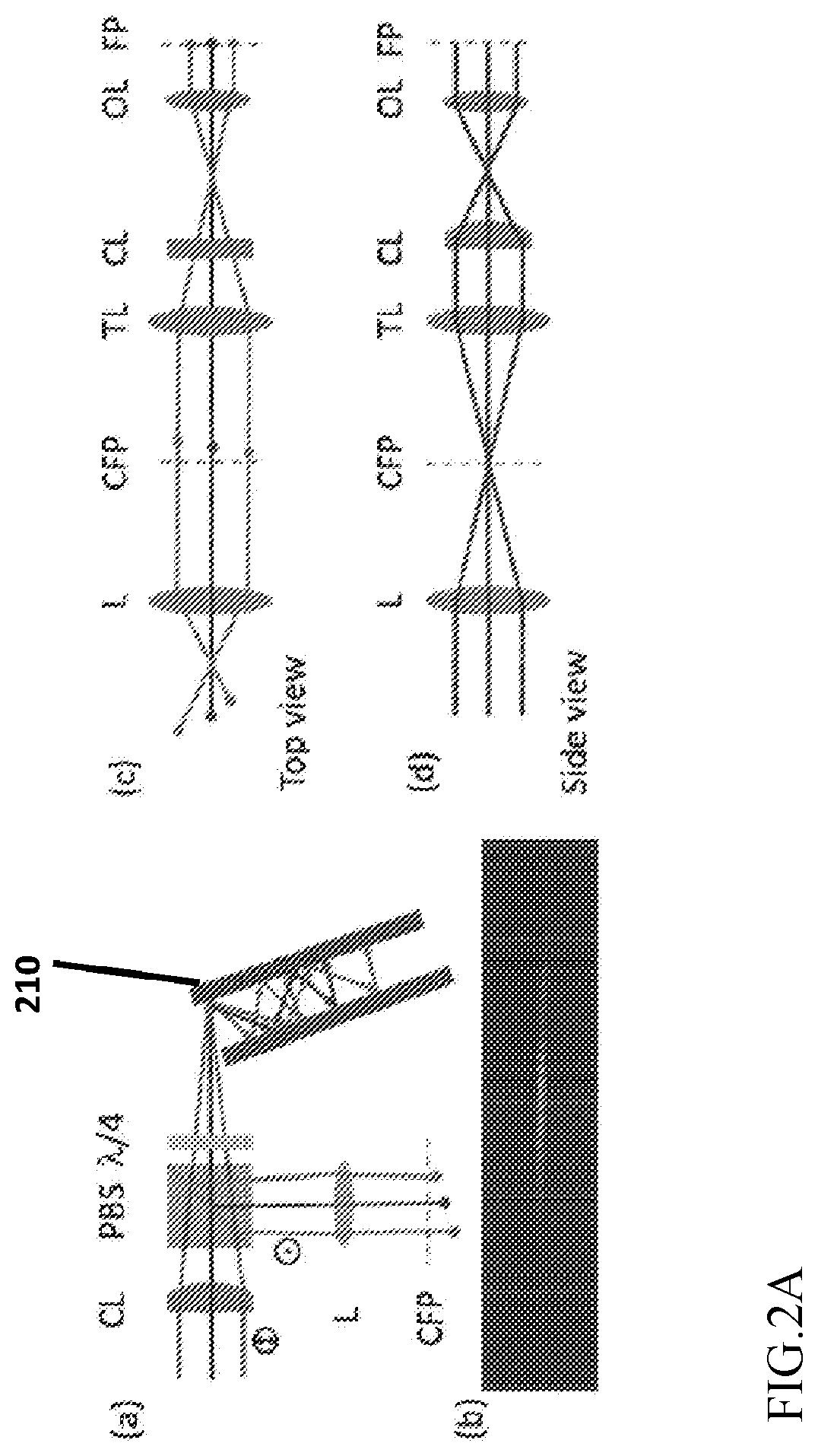
A microscopy device comprises a continuous or pulsed wave laser light source; a pair of parallel mirrors configured to receive light from the light source and reflect an array of incoherent light sheets; a beam encoder (e.g., frequency modulation reticle, Hadamard basis, random modulation pattern) to segment the array of incoherent light sheets and encode each light sheet with a respective frequency in reciprocal space; a lens configured to direct the encoded light sheets towards a biological sample; and an image capturing device configured to receive a fluorescence signal from the biological sample.

Description

BACKGROUND OF THE INVENTION[0001]Biological imaging has been utilized for imaging physiologically relevant systems for many years.[0002]The grand challenge of understanding the animate processes of complex biological systems in three-dimension (3D) lies in the lack of imaging modalities that enable monitoring of the dynamics at sufficiently high spatiotemporal resolution and with low level of photodamage. Established 3D biological imaging techniques, namely confocal and multiphoton microscopy, and light Sheet Fluorescence Microscopy (LSFM) is a biological imaging technique that operates by decoupling the illumination and detection optical pathways; and uses different illumination techniques to optimize the photon collecting efficiency of the system. However, these light-based imaging systems can cause photo-damage and induce photo-toxicity in a biological sample. These light-based imaging systems predominantly rely on the laser scanning that often compromises imaging speed because t...

Claims


Application Information

Patent Timeline
IPC IPC(8): G02B21/00G02B21/36G01N21/64
CPCG02B21/0076G02B21/0032G01N21/6486G01N21/6458G02B21/367G02B21/16G02B21/002G01N21/8851
Inventor TSIA, KEVIN KIN MANREN, YUXUANWU, JIANGLAILAU, ANDY KAM SENGLAI, QUEENIE TSZ KWAN
Owner THE UNIVERSITY OF HONG KONG
Learn More