
Reduced diameter optical fiber with improved microbending

a technology of optical fibers and microbending, applied in the field of optical fiber cables, can solve the problems of reducing the number of channels and channel data rates, rendering these approaches no longer practical, and the approach is also not practical, so as to increase the fiber count of submarine cables, reduce the diameter, and facilitate deploymen

Pending Publication Date: 2021-09-23
CORNING INC
View PDF2 Cites 3 Cited by
  • Summary
  • Abstract
  • Description
  • Claims
  • Application Information

AI Technical Summary

Benefits of technology

The present patent provides optical fibers that can be used in submarine cables to increase the fiber count without increasing the diameter. These fibers have a reduced glass diameter and / or coating thickness while still maintaining good transmission properties. The reduced fiber size allows for a higher fiber density in submarine cables. The microbending properties of these fibers are achieved by optimizing the coating properties and inhibiting signal leakage. The secondary coating also improves puncture resistance and handleability of the fiber despite its smaller size.

Problems solved by technology

However, the number of channels and channel data rate are nearly at the practical limits, thus rendering these approaches no longer practical.
However, this approach is also not practical as the diameter of submarine cables is limited in order to provide easy deployment of the cables.
Increasing the diameter of the submarine cable makes the cables harder to manage due to the increased weight and the limited storage capacity on the ships that deploy undersea optical cables.

Method used


Image

  • Reduced diameter optical fiber with improved microbending
  • Reduced diameter optical fiber with improved microbending
  • Reduced diameter optical fiber with improved microbending

Examples


Embodiment Construction

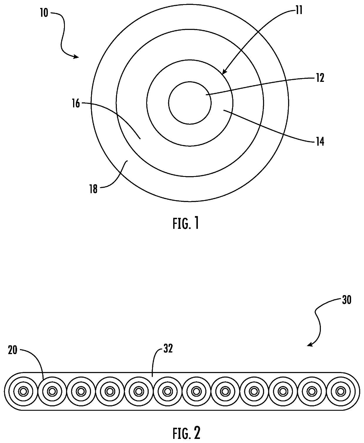
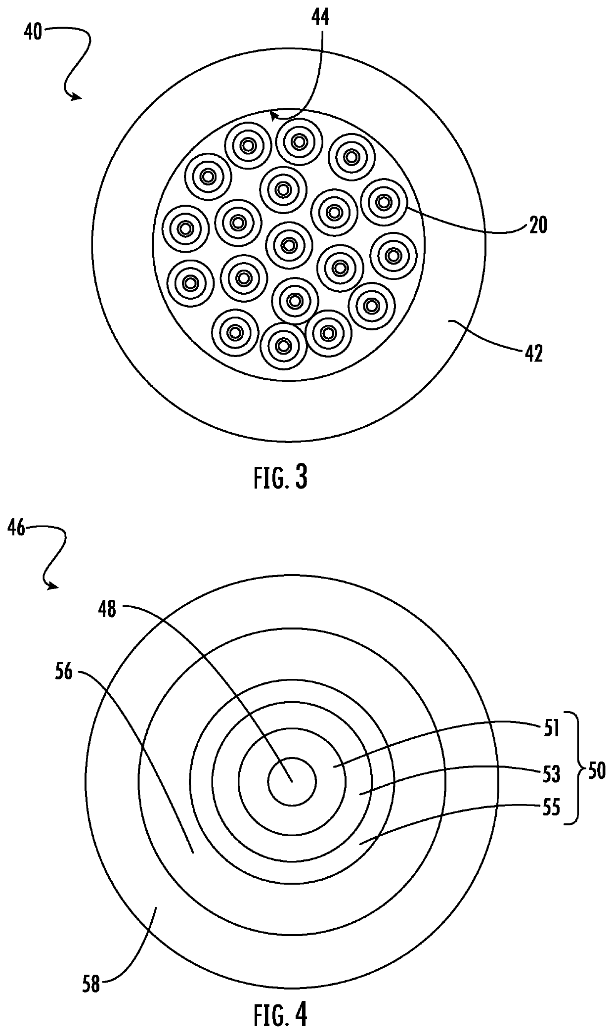
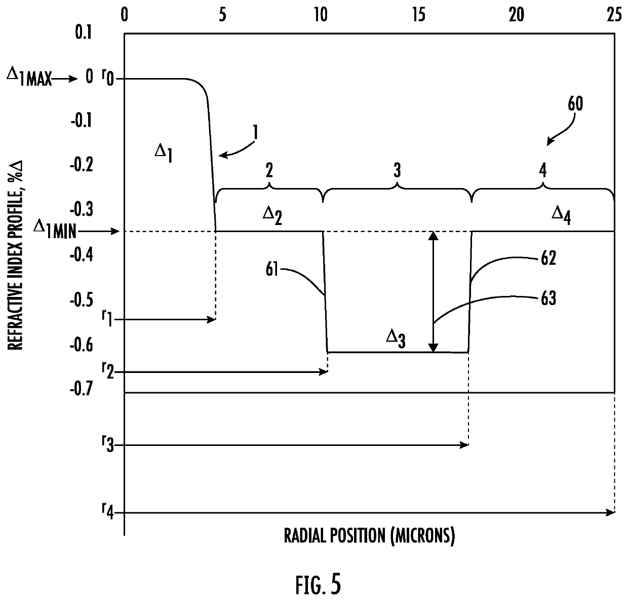
[0025]The present disclosure is provided as an enabling teaching and can be understood more readily by reference to the following description, drawings, examples, and claims. To this end, those skilled in the relevant art will recognize and appreciate that many changes can be made to the various aspects of the embodiments described herein, while still obtaining the beneficial results. It will also be apparent that some of the desired benefits of the present embodiments can be obtained by selecting some of the features without utilizing other features. Accordingly, those who work in the art will recognize that many modifications and adaptations are possible and can even be desirable in certain circumstances and are a part of the present disclosure. Therefore, it is to be understood that this disclosure is not limited to the specific compositions, articles, devices, and methods disclosed unless otherwise specified. It is also to be understood that the terminology used herein is for th...


PUM

PropertyMeasurementUnit
areaaaaaaaaaaa
widthaaaaaaaaaa
widthaaaaaaaaaa

Abstract

A multicore optical fiber is provided that includes a first core with silica glass doped with chlorine and / or an alkali metal, a first inner cladding surrounding the first core, and a first outer cladding surrounding the first inner cladding and having a first trench region having a volume of about 30%Δ-micron2 or greater. The multicore optical fiber also includes a second core with silica glass doped with chlorine and / or an alkali metal, a second inner cladding surrounding the second core, and a second outer cladding surrounding the second inner cladding and having a second trench region having a volume of about 30%Δ-micron2 or greater. Additionally, a common cladding surrounds the first core and the second core, and the first core and the second core each have an effective area at 1550 nm of about 100 micron2 or less.

Description

[0001]This application claims the benefit of priority to Dutch Patent Application No. 2025271 filed on Apr. 3, 2020, which claims priority from U.S. Provisional Patent Application Ser. No. 62 / 991,278 filed on Mar. 18, 2020, the content of which is relied upon and incorporated herein by reference in its entirety.FIELD OF THE DISCLOSURE[0002]This disclosure pertains to optical fibers. More particularly, this disclosure pertains to optical fiber cables configured for submarine environments. Most particularly, this disclosure pertains to optical fibers having reduced diameters without a significant increase in microbending sensitivity.BACKGROUND OF THE DISCLOSURE[0003]Submarine cables are designed to carry telecommunication signals across stretches of land ocean and sea. Over the past several years, there has been a dramatic increase in telecommunications signals over submarine cables, with greater than ninety percent of inter-continental communication signals currently being transmitte...

Claims


Application Information

Patent Timeline
Patent Type & Authority Applications(United States)
IPC IPC(8): G02B6/02G02B6/44G02B6/028C03C25/106
CPCG02B6/02395C03C25/106G02B6/0288G02B6/4403G02B6/02042G02B6/02014G02B6/0365G02B6/02019G02B6/4427
Inventor BENNETT, KEVIN WALLACEMISHRA, SNIGDHARAJ KUMARTANDON, PUSHKARZAKHARIAN, ARAMAIS ROBERT
Owner CORNING INC
Learn More