System and method for formulating medical treatment effluents
a technology of medical treatment effluent and system and method, which is applied in the direction of water/sewage treatment by oxidation, water treatment compounds, disinfection, etc., can solve the problems of poor diffusion, large loss of oxygen in diffusion methods, and/or substantial monetary costs, etc., and achieves convenient design
- Summary
- Abstract
- Description
- Claims
- Application Information
AI Technical Summary
Benefits of technology
Problems solved by technology
Method used
Image
Examples
first embodiment
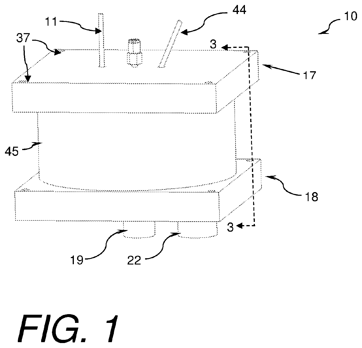
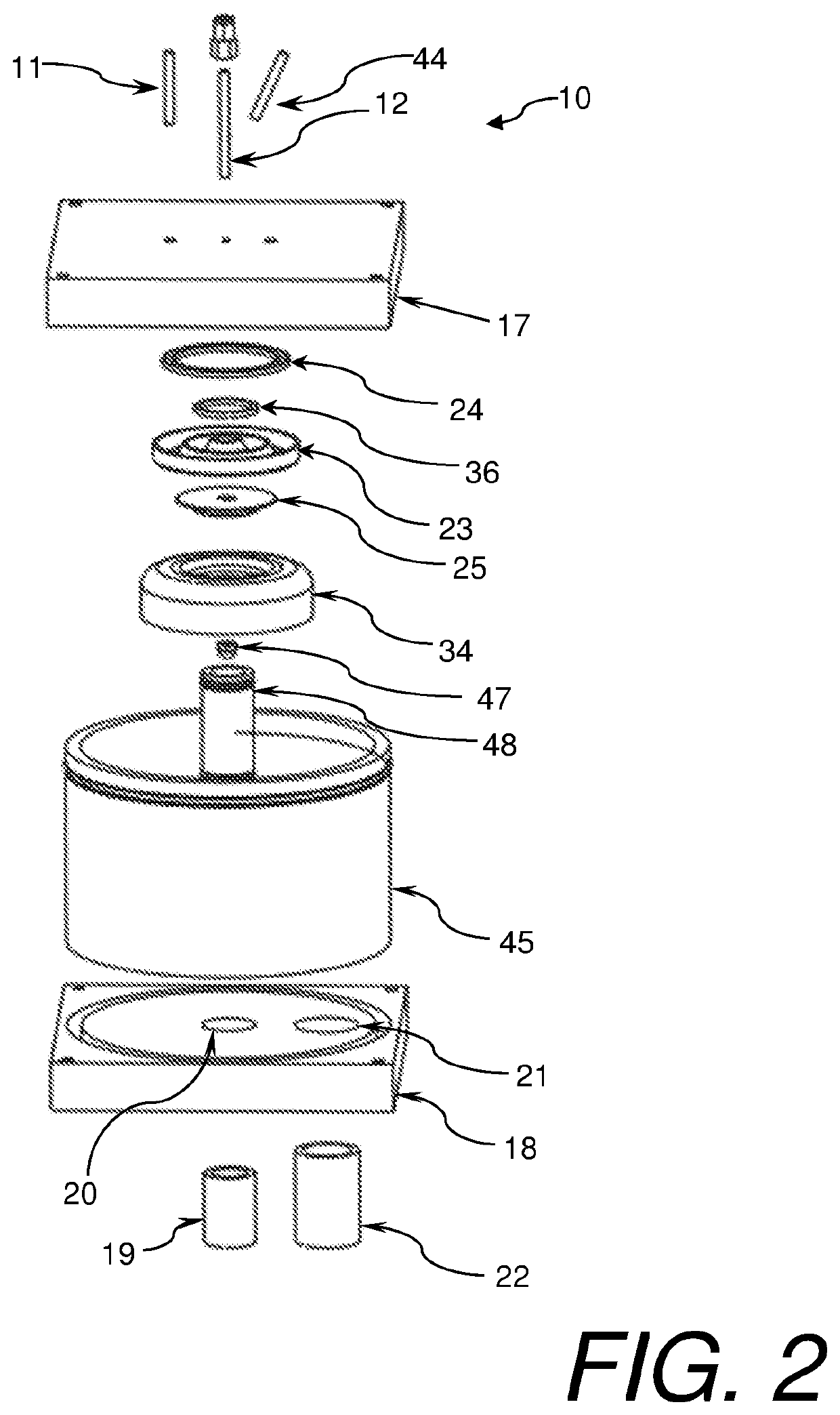
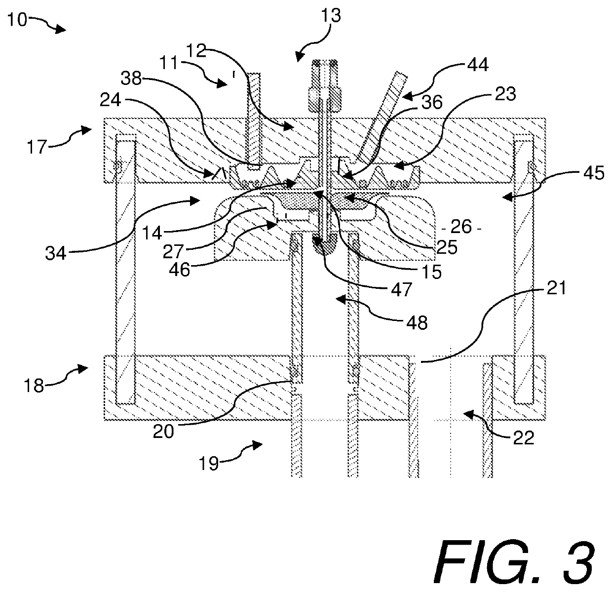
[0042]Referring to FIGS. 1-5, a plasma reactor 10, constructed in accordance with at least the current invention, is shown. The reactor 10 generally receives a gas, a liquid, and electrical stimulus as inputs. The gas may be ionized to form a plasma over the liquid which is in contact with the liquid. The ionized gas interacts with the liquid to create an effluent or product. The plasma reactor 10 broadly comprises a lower housing 18, a housing wall 45, an upper housing 17, at least one dielectric element 23, an upper flow spreader 25, a lower flow spreader 34, first electrode(s) 24, a second electrode which may be the lower flow spreader 34 or another second electrode configuration herein described, and a reaction or effluent chamber 26. The reactor may also include an optional pre-ionization electrode 36. An electric field generator may be attached to the first and second electrodes. In cases where an optional pre-ionization electrode is utilized, an electric field generator may b...
second embodiment
[0063]Referring to FIG. 6, the reactor utilizes a dielectrically isolated second electrode 29. In some applications which may include oxygen and ultra-high purity water, it may be desirable to avoid any liquid contact with metallic elements or elements that are conducting electricity. Other applications where this is desirable may include applications where the liquid is not able to be connected to an electrical potential. There are other applications that may benefit from a dielectric isolation not listed here. In these applications the second electrode may be dielectrically isolated from the liquid by using a second electrode 29. This electrode may be placed in the lower flow spreader 34 and covered with a material such as ceramic, polymer, or other materials known by those familiar with the art to isolate the alternate electrode 29 from the liquid stream. In these cases the electrical field will be shared by the dielectric element 23, the gas flow below the dielectric element, th...
third embodiment
[0064]Referring to FIG. 7, this reactor may split the first electrode into several alternate first electrodes 41. These alternate first electrodes 41 may be annular or other shapes, may be located in the internal cavity 38, and may be isolated from the reactor chamber 26 by the dielectric element 23. In addition, this type of electrode may be used for alternate optional pre-ionization electrodes 49. By using multiple electrodes, the electrical characteristic of a reactor of a given size may be altered thereby enabling a greater plasma area without a corresponding increase in electrode capacitance and simplifying the design of the electrical source to drive the electric field required to generate a plasma. One or more first electrodes may be used in a given reactor. One or more optional pre-ionization electrodes may be used in a reactor. The use of a type of one or more first electrodes in a given reactor may depend on the reactor size, type of reaction desired, and / or other consider...
PUM
 Abstract
Description
Claims
Application Information
 - R&D
- Intellectual Property
- Life Sciences
- Materials
- Tech Scout
- Unparalleled Data Quality
- Higher Quality Content
- 60% Fewer Hallucinations
Browse by: Latest US Patents, China's latest patents, Technical Efficacy Thesaurus, Application Domain, Technology Topic, Popular Technical Reports.
© 2025 PatSnap. All rights reserved.Legal|Privacy policy|Modern Slavery Act Transparency Statement|Sitemap|About US| Contact US: help@patsnap.com


