Polymerisable compounds and the use thereof in liquid-crystal displays

a technology of liquid crystal display and polymerisable compounds, which is applied in the field of polymerisable compounds and the use thereof in liquid crystal display, can solve the problems of reducing the transparency of light, the disadvantage of strong viewing angle dependence of contrast of tn lcds, and the lengthening of response times, so as to facilitate a quick and complete uv-photopolymerisation reaction and reduce image sticking and odf mura in the display. , the effect o

Active Publication Date: 2021-05-13
MERCK PATENT GMBH
View PDF1 Cites 1 Cited by
  • Summary
  • Abstract
  • Description
  • Claims
  • Application Information

AI Technical Summary

Benefits of technology

[0051]It was surprisingly found that the use of these RMs, and of LC media comprising them, in PSA displays facilitates a quick and complete UV-photopolymerisation reaction in particular at longer UV wavelengths in the range from 300-380 nm and especially above 320 nm, even without the addition of photoinitiator, leads to a fast generation of a large and stable pretilt angle, reduces image sticking and ODF mura in the display, leads to a high reliability and a high VHR value after UV photopolymerisation, especially in case of LC host mixtures containing LC compounds with an alkenyl group, and enables to achieve fast response times, a low threshold voltage and a high birefringence.
[0052]In addition, the RMs according to the invention have low melting points, good solubility in a wide range of LC media, especially in commercially available LC host mixtures for PSA use, and a low tendency to crystallisation. Besides, they show good absorption at longer UV wavelengths, in particular in the range from 300-380 nm, and enable a quick and complete polymerisation with small amounts of residual, unreacted RMs in the cell.
[0053]Also, it was surprisingly found that the RMs according to the present invention combine a fast polymerisation speed, which is similar to that of terphenyl RMs, with good reliability parameters similar to biphenyl RMs. This results in a superior overall performance compared to RMs of the state of the art.
[0054]WO 2014 / 142168 A1 discloses an LC aligning agent containing crosslinkable compounds with a photoreactive group, and explicitly discloses the following compound
[0055]However, this document does neither disclose nor suggest RMs as disclosed and claimed hereinafter, or their use in PSA displays and the advantages thereby achieved.
[0056]The invention relates to compounds of formula I

Problems solved by technology

However, TN LCDs have the disadvantage of a strong viewing-angle dependence of the contrast.
Although this arrangement improves the viewing angle of the display, it results, however, in a reduction in its transparency to light.
For further improvement of the transparency to light, the separations between the slits and protrusions can be increased, but this in turn results in a lengthening of the response times. In so-called PVA (“patterned VA”) displays, protrusions are rendered completely superfluous in that both electrodes are structured by means of slits on the opposite sides, which results in increased contrast and improved transparency to light, but is technologically difficult and makes the display more sensitive to mechanical influences (“tapping”, etc.).
However, the rubbing process causes a number of problems, like mura, contamination, problems with static discharge, debris, etc.
Generally the effort and costs for production of such a polyimide layer, treatment of the poylimide and improvement with bumps or polymer layers are relatively great.
In addition, it was observed that unfavourable interaction of the polyimide alignment layer with certain compounds of the LC medium often leads to a reduction of the electrical resistance of the display.
However, the problem arises that not all combinations consisting of an LC mixture and one or more RMs are suitable for use in PSA displays because, for example, an inadequate tilt or none at all becomes established or since, for example, the VHR is inadequate for TFT display applications.
Thus, not every known RM which is soluble in LC mixtures is suitable for use in PSA displays.
In addition, it is often difficult to find a suitable selection criterion for the RM besides direct measurement of the pretilt in the PSA display.
A further problem in the production of PSA displays is the presence or removal of residual amounts of unpolymerised RMs, in particular after the polymerisation step for production of the pretilt angle in the display.
For example, unreacted RMs of this type may adversely affect the properties of the display by, for example, polymerising in an uncontrolled manner during operation after finishing of the display.
Thus, the PSA displays known from the prior art often exhibit the undesired effect of so-called “image sticking” or “image burn”, i.e. the image produced in the LC display by temporary addressing of individual pixels still remains visible even after the electric field in these pixels has been switched off or after other pixels have been addressed.
The UV component of daylight or the backlighting can cause undesired decomposition reactions of the LC molecules therein and thus initiate the production of ionic or free-radical impurities.
These may accumulate, in particular, at the electrodes or the alignment layers, where they may reduce the effective applied voltage.
A further problem that has been observed in the operation of PSA displays is the stability of the pretilt angle.
Thus, it was observed that the pretilt angle, which was generated during display manufacture by polymerising the RM as described above, does not remain constant but can deteriorate after the display was subjected to voltage stress during its operation.
This can negatively affect the display performance, e.g. by increasing the black state transmission and hence lowering the contrast.
Another problem to be solved is that the RMs of prior art do often have high melting points, and do only show limited solubility in many currently common LC mixtures, and therefore frequently tend to spontaneously crystallise out of the mixture.
In addition, the risk of spontaneous polymerisation prevents the LC host mixture being warmed in order to dissolve the polymerisable component, meaning that the best possible solubility even at room temperature is necessary.
In addition, there is a risk of separation, for example on introduction of the LC medium into the LC display (chromatography effect), which may greatly impair the homogeneity of the display.
Another problem observed in prior art is that the use of conventional LC media in LC displays, including but not limited to displays of the PSA type, often leads to the occurrence of mura in the display, especially when the LC medium is filled in the display cell manufactured using the one drop filling (ODF) method.
Another problem observed in prior art is that LC media for use in PSA displays, including but not limited to displays of the PSA type, do often exhibit high viscosities and, as a consequence, high switching times. In order to reduce the viscosity and switching time of the LC medium, it has been suggested in prior art to add LC compounds with an alkenyl group.
However, it was observed that LC media containing alkenyl compounds often show a decrease of the reliability and stability, and a decrease of the VHR especially after exposure to UV radiation.
Especially for use in PSA displays this is a considerable disadvantage, because the photo-polymerisation of the RMs in the PSA display is usually carried out by exposure to UV radiation, which may cause a VHR drop in the LC medium.
Biphenyl RMs were shown to exhibit limited polymerisation speed but good reliability parameters, like high VHR or tilt stability, while terphenyl RMs were shown to exhibit fast polymerisation speed but limited reliability parameters.
However, this document does neither disclose nor suggest RMs as disclosed and claimed hereinafter, or their use in PSA displays and the advantages thereby achieved.

Method used


Image

  • Polymerisable compounds and the use thereof in liquid-crystal displays
  • Polymerisable compounds and the use thereof in liquid-crystal displays
  • Polymerisable compounds and the use thereof in liquid-crystal displays

Examples


example 1

able Compounds

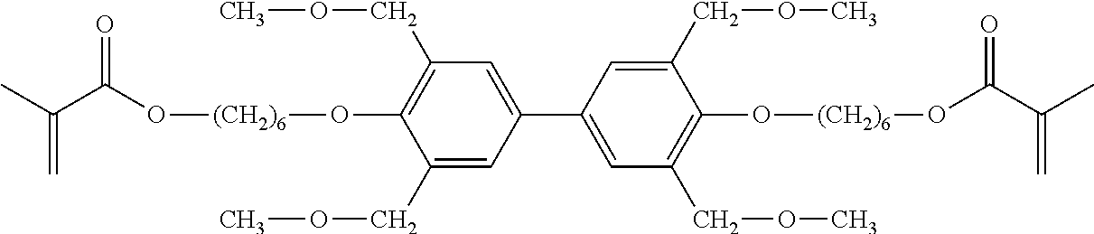
[0538]Polymerisable compound (or “RM”) 1 is prepared as follows

[0539]1.4: A suspension of sodium hydride (5.4 g, 60% in mineral oil, 135.6 mmol) was added to a stirred solution of benzyl alcohol 1.3 (20.0 g, 113.0 mmol) in THF (20 mL) at 0° C. The resulting mixture was stirred for 10 min at the same temperature before it was treated with methyl iodide (8.7 mL, 135.6 mmol). The reaction mixture was stirred for 4 hours at ambient temperature, carefully quenched with water and extracted with ethyl acetate. Aqueous phase was separated and extracted with ethyl acetate (2 times). The combined organic phase was washed with sat. NaCl solution, dried over Na2SO4, filtered and concentrated in vacuo. The residue was purified with flash chromatography (heptane) to give 1.4 as a colorless oil. (21.0 g, 97%; GC: 99.9%).

[0540]1.6: Hydrazine hydrate (0.2 mL, 80%, 0.004 mol) was added to a stirred solution of sodium metaborate tetrahydrate (43.3 g, 0.314 mol) and PdCl2[P(cy)3]2 (3.1 g,...

example 2

able Mixtures

[0547]The nematic LC host mixture N1 is formulated as follows:

CCH-501 9.00%cl.p.70.0° C.CCH-3514.00%Δn  0.0825PCH-53 8.00%Δε−3.5CY-3-O414.00%ε∥  3.5CY-5-O413.00%K3 / K1  1.00CCY-2-1 9.00%γ1  141 mPa sCCY-3-1 9.00%V0 2.10 VCCY-3-O2 8.00%CCY-5-O2 8.00%CPY-2-O2 8.00%

[0548]The nematic LC host mixture N2 is formulated as follows:

CY-3-O218.00%cl.p.+74.5° C.CPY-2-O210.00%Δn  0.1021CPY-3-O210.00%Δε−3.1CCY-3-O2 9.00%ε∥  3.5CCY-4-O2 4.00%K3 / K1  1.16PYP-2-3 9.00%γ1     86 m Pa sCC-3-V40.00%V0   2.29 V

[0549]The nematic LC host mixture N3 is formulated as follows:

CC-3-V1 9.00%cl.p.CCH-2314.00%ΔnCCH-34 6.00%ΔεCCH-35 6.00%ε∥CCP-3-1 7.00%K3 / K1CCY-3-O1 5.00%γ1CCY-3-O210.00%V0CPY-3-O212.00%CY-3-O2 9.50%PP-1-2V1 8.50%PY-3-O212.00%PY-4-O2 1.00%

[0550]Polymerisable mixtures P11, P21 and P31 according to the present invention are prepared by adding polymerisable compound RM1 of Example 1 to nematic LC host mixture N1, N2 or N3, respectively.

[0551]For comparison purpose, polymerisable mixtures C...

example 3

les

[0553]The individual polymerisable mixtures are filled into PSA test cells, the RM is polymerised under application of a voltage, and several properties like residual RM content, VHR under UV stress, tilt angle generation and tilt angle stability are measured.

Residual RM Measurement

[0554]The polymerisation speed is measured by determining the residual content of residual, unpolymerised RM (in % by weight) in the mixture after UV exposure with a given intensity and lamp spectrum after a given UV exposure time. The smaller the residual RM content after a given time interval, the faster the polymerization,

[0555]For this purpose the polymerisable mixtures are filled into electrooptic test cells made of soda lime glass coated with an approximately 200 nm thick layer of ITO and a 30 nm layer of VA-polyimide from Varitronix with a cell gap of 6-7 μm

[0556]The test cells are illuminated by a MH-lamp (UV-Cube 2000) using a 320 nm long pass filter (N-WG320) and a light intensity of 100 mW / c...


PUM

PropertyMeasurementUnit
tilt angleaaaaaaaaaa
wavelengthsaaaaaaaaaa

Abstract

The present invention relates to polymerisable compounds, to processes and intermediates for the preparation thereof, to liquid-crystal (LC) media comprising them, and to the use of the polymerisable compounds and LC media for optical, electro-optical and electronic purposes, in particular in LC displays, especially in LC displays of the polymer sustained alignment type.

Description

[0001]The present invention relates to polymerisable compounds, to processes and intermediates for the preparation thereof, to liquid-crystal (LC) media comprising them, and to the use of the polymerisable compounds and LC media for optical, electro-optical and electronic purposes, in particular in LC displays, especially in LC displays of the polymer sustained alignment type.BACKGROUND OF THE INVENTION[0002]One of the liquid-crystal display (LCD) modes used at present is the TN (“twisted nematic”) mode. However, TN LCDs have the disadvantage of a strong viewing-angle dependence of the contrast.[0003]In addition, so-called VA (“vertically aligned”) displays are known which have a broader viewing angle. The LC cell of a VA display contains a layer of an LC medium between two transparent electrodes, where the LC medium usually has a negative dielectric anisotropy. In the switched-off state, the molecules of the LC layer are aligned perpendicular to the electrode surfaces (homeotropica...

Claims


Application Information

Patent Timeline
Patent Type & Authority Applications(United States)
IPC IPC(8): C09K19/56C09K19/30C07C69/017G02F1/1343
CPCC09K19/56C09K19/3003C07C69/017C09K2019/3016C09K2019/3004C09K2019/3009C09K2019/301G02F1/134309C09K2019/0425C09K19/04C09K2019/0448C09K2019/122C09K2019/123C09K2019/3027
Inventor USHAKOV, DMITRYDEING, KAJA CHRISTINATONG, QIONG
Owner MERCK PATENT GMBH
Why Eureka
Try Eureka