
Nanocomposite coating for antenna reflector and methods of making same

a technology of nanocomposite coating and antenna reflector, which is applied in nanotechnology, coatings, antennas, etc., can solve the problems of increasing the weight of antennas, reducing the payload of space stations, and metallic antennas being susceptible to electromagnetic interference, so as to enhance one or more electromagnetic characteristics of antenna reflectors and low weight

Active Publication Date: 2021-04-15
RAFIEE ROHAM
View PDF0 Cites 1 Cited by
  • Summary
  • Abstract
  • Description
  • Claims
  • Application Information

AI Technical Summary

Benefits of technology

The nanocomposite coating composition effectively enhances the electromagnetic properties of polymeric composite antennas, reducing weight and electromagnetic interference while maintaining efficient data transmission and reception in the Ku frequency band, without the need for additional metallic mesh or fillers.

Problems solved by technology

The metallic antenna is quite heavy and it either requires facilities for positioning in ground stations or it results in a considerable reduction in the payload for space stations.
Hence, the metallic antennas are susceptible to cause electromagnetic interference, especially for satellite broadcasting.
Therefore, the incorporation of high-density meshes within the small cells is necessary, which would increase the weight of antennas.

Method used


Image

  • Nanocomposite coating for antenna reflector and methods of making same
  • Nanocomposite coating for antenna reflector and methods of making same
  • Nanocomposite coating for antenna reflector and methods of making same

Examples


example — 1

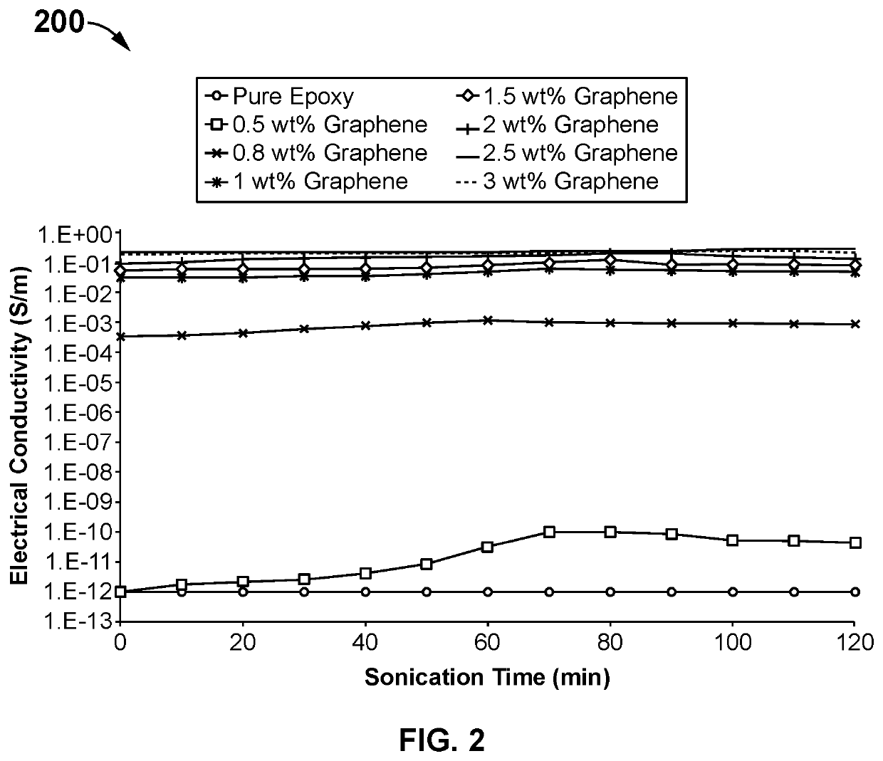
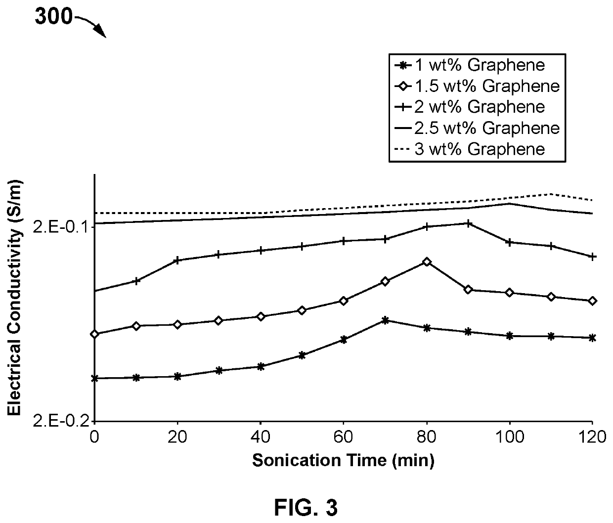
Example—1:—Electrical Conductivity

[0042]The electrical conductivity of the fabricated nanocomposite specimens is examined using a standardized four-point connection. A digital multimeter is employed to measure the current and resistance of the specimen / sample [2]. Upon the readings of the digital multimeter, the volume density is calculated using the equation (1). The volume density is used to calculate the electrical conductivity of the sample [2] using the equation (2):

ρ=RA / L  (1)

σ=1 / ρ  (2)

where “R” represents the electrical resistance (in Ω), “ρ” represents specific volume density (in Ωcm), “σ” represents DC electrical conductivity (in S / cm), “A” represents the area (in cm) and “L” represents the thickness of specimen (in cm).

example — 2

Example—2:—Permittivity

[0043]The performance of the materials in electromagnetic environments is characterized using the complex permittivity [3]. The relative permittivity comprises a real part of complex permittivity or dielectric constant or energy storage, and an imaginary part of complex permittivity or dielectric loss. The complex permittivity is expressed as below [4]:

εr=ε′+iε″   (3)

where εr represents complex relative permittivity, ε′ represents dielectric constant, and ε″ represents dielectric loss. The complex permittivity could be indirectly measured using scattering parameters with VNA (Vector Network Analyzer).

example — 3

Example—3:—Skin Depth

[0044]The skin depth describes the capability of the electromagnetic field emitted in a material and indicates the minimum required thickness for transmitting the electric current. The specimens having with a lesser thickness of skin depth provides a higher reflection rate. Hence, the current is transmitted to the upper layers of the specimens, which leads to the improvement in the electromagnetic properties of the material. Therefore, the electric conductivity of the material depends on the skin depth and the frequency of the applied waves. A perfect electric conductor has zero skin depth. For instance, the skin depth of a good electric conductor such as aluminum in Ku frequency band is about 0.736 to 0.611 μm. The Ku frequency band has a frequency range from 12.4 to 18 GHz with a relative permeability of one and resistivity of 2.65e-8. The skin depth is expressed in terms of frequency, electrical conductivity, and electromagnetic permittivity as below [5]:

δ−[ρ...


PUM

PropertyMeasurementUnit
viscosityaaaaaaaaaa
densityaaaaaaaaaa
electrical conductivityaaaaaaaaaa

Abstract

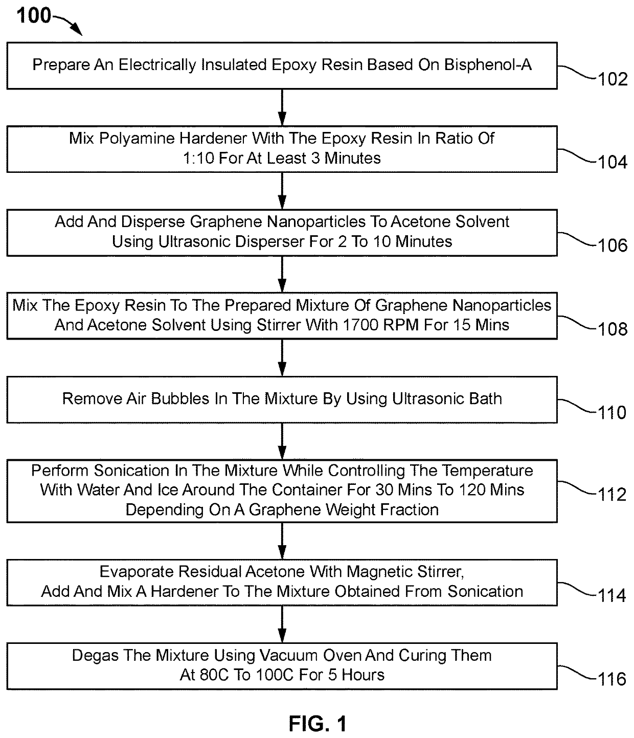
The present invention discloses a nanocomposite coating composition and coating method for antenna reflector. The nanocomposite coating composition comprises a polymer matrix resin and a plurality of graphene nanoparticles. A portion of hardener is firstly added into epoxy resin system. The plurality of graphene nanoparticles is added to acetone solvent and dispersed using an ultrasonic disperser. An appropriate amount of prepared epoxy resin is added to the mixture of graphene and acetone solvent and stirred using a mechanical stirrer for certain period. The sonication process is applied to the graphene incorporated resin mixture for a duration of about 30-120 minutes. The acetone in the mixture is removed using a magnetic stirrer and a vacuum oven. Further, the remainder of the hardener is added to the mixture and degassed using vacuum oven to form the nanocomposite coating composition. The nanocomposite coating composition converts an electromagnetically insulated antenna into an electromagnetically conductive antenna for enhancing one or more electromagnetic characteristics of the antenna reflector.

Description

BACKGROUND OF THE INVENTION[0001]The communication and broadcasting systems receive / transmit information in a form of signal from a satellite. Conventional systems use many types of antennas or antenna reflectors such as dish antennas and Rotman lenses, to transmit / receive signal in the form of electromagnetic waves from the satellite. The existing antenna reflectors are divided into two main groups namely, metallic antennas and composite antennas.[0002]The metallic antennas are made of metallic materials or conductive materials, which are widely used in satellite communication based on their electromagnetic reflecting property. The metallic antenna is quite heavy and it either requires facilities for positioning in ground stations or it results in a considerable reduction in the payload for space stations. Moreover, the metallic materials transmit / receive the electromagnetic waves regardless of the frequency range. Hence, the metallic antennas are susceptible to cause electromagnet...

Claims


Application Information

Patent Timeline
Patent Type & Authority Applications(United States)
IPC IPC(8): C09D5/24C09D163/00C09D7/80C09D7/40H01Q1/36H01Q15/14
CPCC09D5/24C09D163/00C09D7/80C08K3/042H01Q1/368H01Q15/14C09D7/67B82Y30/00C08G59/50C08K2201/011C09D7/70B82Y40/00C08K2201/001
Inventor RAFIEE, ROHAM
Owner RAFIEE ROHAM
Learn More