
Concentric cylindrical circumferential laser

a laser and concentric cylindrical technology, applied in the direction of laser details, active medium shape and construction, semiconductor lasers, etc., can solve the problems of limiting micro-cavity laser resonators to very low power applications, optical cavity resonators losing their resonant properties,

Active Publication Date: 2021-04-08
LACOMB RONALD +1
View PDF37 Cites 5 Cited by
  • Summary
  • Abstract
  • Description
  • Claims
  • Application Information

AI Technical Summary

Benefits of technology

The patent describes a new type of laser apparatus that uses a cylindrical ring optical resonator. This resonator has a gain media that is pumped by a pump source to create a confining region that limits the optical gain in the resonator. The resonator supports a plurality of modes, including radial and axial modes. The pump source overlaps with the gain media to generate photons within the confining region. The resonator also favors amplification of a subset of modes that support circumferential radiative emission in the radial direction. The laser apparatus can be made using a semiconductor or solid-state laser media and can be used in a multi-element laser array. The technical effects of this invention include improved laser efficiency, reduced laser size, and improved laser control.

Problems solved by technology

Use of optical cavity resonators for V>λ3 is not practical as the separation between resonances, i.e. the ratio of ΔM / ω decreases with frequency, while spectral line ω / Q increases with frequency.
Optical cavity resonators are therefore limited to micro-cavity resonators with geometries on order with the optical wavelength (1-100λ), exceeding this criterion causes optical cavity resonators to lose their resonant properties, limiting micro-cavity type laser resonators to very low power applications.
Since traveling wave disk resonators are a form of cavity resonator, their geometries are limited to micro-resonators.
As disk diameters become much larger than the operational wavelength the energy separation between modes becomes so small that the resonator cannot differentiate between different wavelengths and therefore loses its resonator behavior.
These waveguides are also micro-resonators with waveguides designed to trap the light around the circumference of the cylinder, sphere, toroid or other circular geometry, which typically limit their application to relatively low output powers less than 10 mW.
Thus, the device of An is not capable of operating at a scale out of the microcavity regime.
Although light emitting diodes (LED) rely upon similar mathematical principles and materials to generate photon emissions, they are not equivalent to laser devices.
In particular, LEDs lack optical resonance and purely directional emission inherent in a single emitter.
Shreter further does not address scaling of laser emitting devices to geometries exceeding the geometries associated with micro-cavity regime.
Conventional electrically actuated photonic devices based upon cylindrically symmetric cavity-type laser resonator architectures are limited to micro-cavity designs with volumes on the order of the optical wavelength as discussed above.
However, Shreter does not address any design considerations, integration strategies, or scaling techniques of the elemental light emitting device design.
Instead, Shreter limits instruction to assembly of laser diode arrays formed by positioning multiple individual conventional cavity-type laser diode resonators about a common axis of symmetry, with possible element candidates limited to conventional laser architectures which are limited to micro-cavity geometries (as above discussed).
Further, as Shreter is absent of any design discussion relating to elemental photon emitters, including optically pumped solid-state laser emitters, his application is limited to bar assembly of conventional electronically actuated photonic sources capable of radial emission which are limited to: light emitting diodes “LEDs” or very low power micro-cavity lasers), and WGM type devices which are all inherently low power elements due to their small cavity volume.
Furthermore, Shreter teaches bar assembly based upon the arrangement of individual light emitting elements positioned along a central axis, no instruction is provided to redesign the individual light emitting elements to possess a common core or discuss arrays with concentric architectures nor address geometric scaling of the individual light emitting elements.
However, power limitations associated with the above designs are often associated with beam width and beam quality degradation or component failure, particularly when scaling to larger volumes or adapting to different geometries.
Typically, as the resonator volume is increased, the resonator modal constituency is altered causing a degradation in beam quality.
Further, increasing the power without increasing the resonator volume can cause thermal degradation or catastrophic optical mirror damage (COD) at the output facet or coupler when power thresholds are exceeded.

Method used


Image

  • Concentric cylindrical circumferential laser
  • Concentric cylindrical circumferential laser
  • Concentric cylindrical circumferential laser

Examples


Embodiment Construction

[0052]As above noted, microcavity lasers, such as those of the type disclosed by An, are restricted to dimensions ranging from a few tens of microns to a few hundreds of microns and are not scalable to larger volumes. The method of optical amplification disclosed by An further restricts volume scaling due to reliance on an external optical source located outside the resonator, evanescently coupled to WGMs supported by the microresonator. Thus, as shown above, the laser architecture disclosed by An is further limited in volume to geometric extents on order with the optical wavelength, and coupled with the absence of gain media within the resonator, no connection can be made to resonator scaling to volumes greater than the optical wavelength. Thus, An cannot achieve scalability to large scale resonators on the order of several inches or greater with high power radial radiative laser emission.

[0053]Also, as above noted, Shreter discloses assembly techniques to form bar arrays of indivi...


PUM

PropertyMeasurementUnit
wavelengthsaaaaaaaaaa
diametersaaaaaaaaaa
output powersaaaaaaaaaa

Abstract

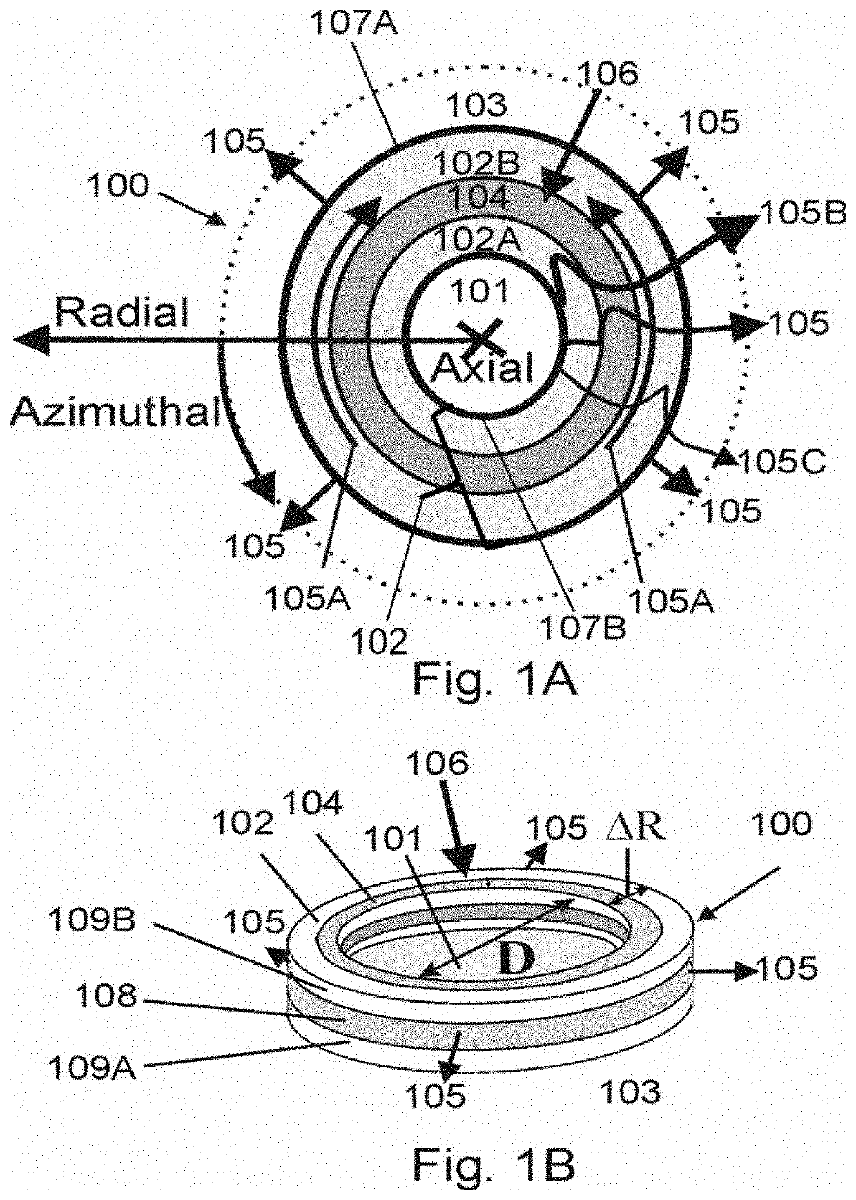
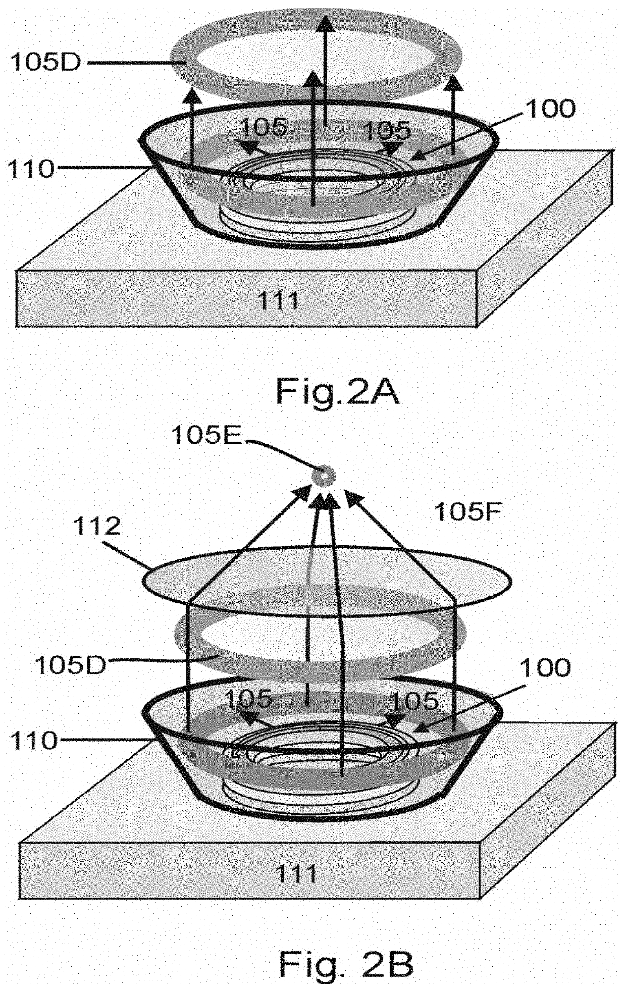
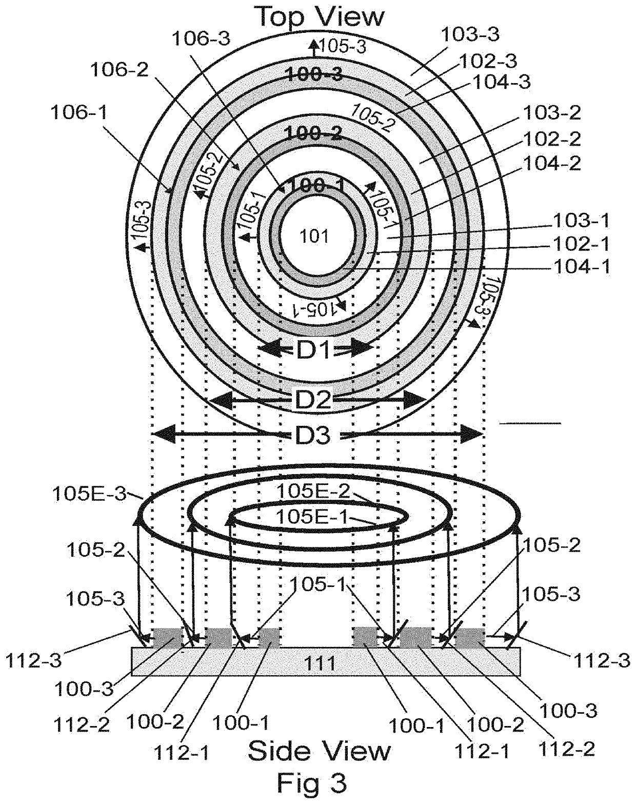
The present disclosure relates to a three-dimensional cylindrical cavity-type laser system capable of supporting circumferential radial emission. A cylindrical ring waveguide provides optical confinement in the radial and axial dimensions thereby supporting a plurality of radial modes, one of a plurality of axial modes and a plurality of degenerate azimuthal modes. These modes constitute a set of traveling wave modes which propagate around the cylindrical ring waveguide possessing various degrees of optical confinement as quantified by their respective Q-factors. Index tailoring is used to tailor the radial refractive index profile and geometry of the waveguide to support radial modes possessing Q-factors capable of producing efficient radial emission, while gain tailoring is used to define a gain confining region which offsets modal gain factors of the modal constituency to favor a preferred set of modes supporting efficient radial emission out of the total modal constituency supported by the resonator. Under appropriate pump actuation the selected modes produce circumferential laser radiation with the output surface comprising of the entire outer perimeter of the cylindrical ring waveguide. The design is applicable toward both micro-resonators and resonators much larger than the optical wavelength, enabling high output powers and scalability. The circumferential radial laser emission can be concentrated by positioning the cylindrical ring laser inside a three-dimensional conical mirror thereby forming a laser ring of light propagating in the axial dimension away from the surface of the laser, which can be subsequently collimated for focused using conventional optics.

Description

APPLICATION CROSS-REFERENCE[0001]This application claims the benefit of U.S. Provisional Application No. 62 / 623,476 filed on Jan. 29, 2018, the entirety of which is incorporated herein by reference. This application is also a continuation-in-part of U.S. patent application Ser. No. 16 / 252,928, filed on Jan. 21, 2019, the entirety of which is herein incorporated by reference.BACKGROUNDTechnical Field[0002]Embodiments of the invention generally fall into the category of a laser apparatus and method of generating a laser beam. In some embodiments there is a cylindrical or circular resonator with a means of mode tailoring utilizing both index of refraction tailoring and gain tailoring to constitute and excite a set of radially emitting modes exiting the resonator along the circumference. In still other embodiments, the circumferential laser emission is directed via three-dimensional reflectors or equivalent structures to image and / or concentrate the laser emission. More specifically, em...

Claims


Application Information

Patent Timeline
Patent Type & Authority Applications(United States)
IPC IPC(8): H01S3/083H01S3/0941H01S3/067H01S3/06
CPCH01S3/083H01S3/0627H01S3/0675H01S3/0941H01S5/1075H01S5/02255H01S2301/203H01S5/4056H01S5/04254H01S5/04256H01S5/204H01S5/2045H01S5/12H01S5/2219H01S5/42H01S5/185H01S5/4075
Inventor LACOMB, RONALD
Owner LACOMB RONALD
Learn More