
Linear optical amplifier using coupled waveguide induced feedback

A technology for optical amplifiers and feedback layers, applied in the field of semiconductor optical amplifiers, can solve problems such as high operating current, gain compression or saturation affecting data transmission, and increasing optical mode size

Inactive Publication Date: 2007-07-11
FINISAR
View PDF0 Cites 0 Cited by
  • Summary
  • Abstract
  • Description
  • Claims
  • Application Information

AI Technical Summary

Problems solved by technology

Increasing the optical mode size, likewise, requires higher material gain to achieve the same amplifier gain, but requires higher operating current
Larger optical modes also lead to higher losses because the optical field overlaps the heavily doped (and thus lossy) semiconductor
[0009] In addition to limiting the linear range of the SOA, gain compression or saturation of the SOA can also affect data transmission by, for example, causing in-channel interference and crosstalk

Method used


Image

  • Linear optical amplifier using coupled waveguide induced feedback
  • Linear optical amplifier using coupled waveguide induced feedback
  • Linear optical amplifier using coupled waveguide induced feedback

Examples


Embodiment Construction

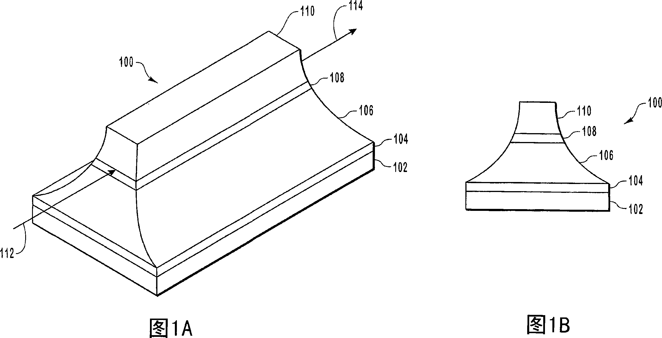
[0028] A semiconductor optical amplifier (SOA) amplifies an optical signal without converting the incident optical signal to an electrical signal. SOAs utilize stimulated emission to amplify incident light signals. However, as mentioned above, SOAs often suffer from gain compression as the output optical power increases. However, gain compression is often accompanied by undesired results such as intersymbol interference and crosstalk.

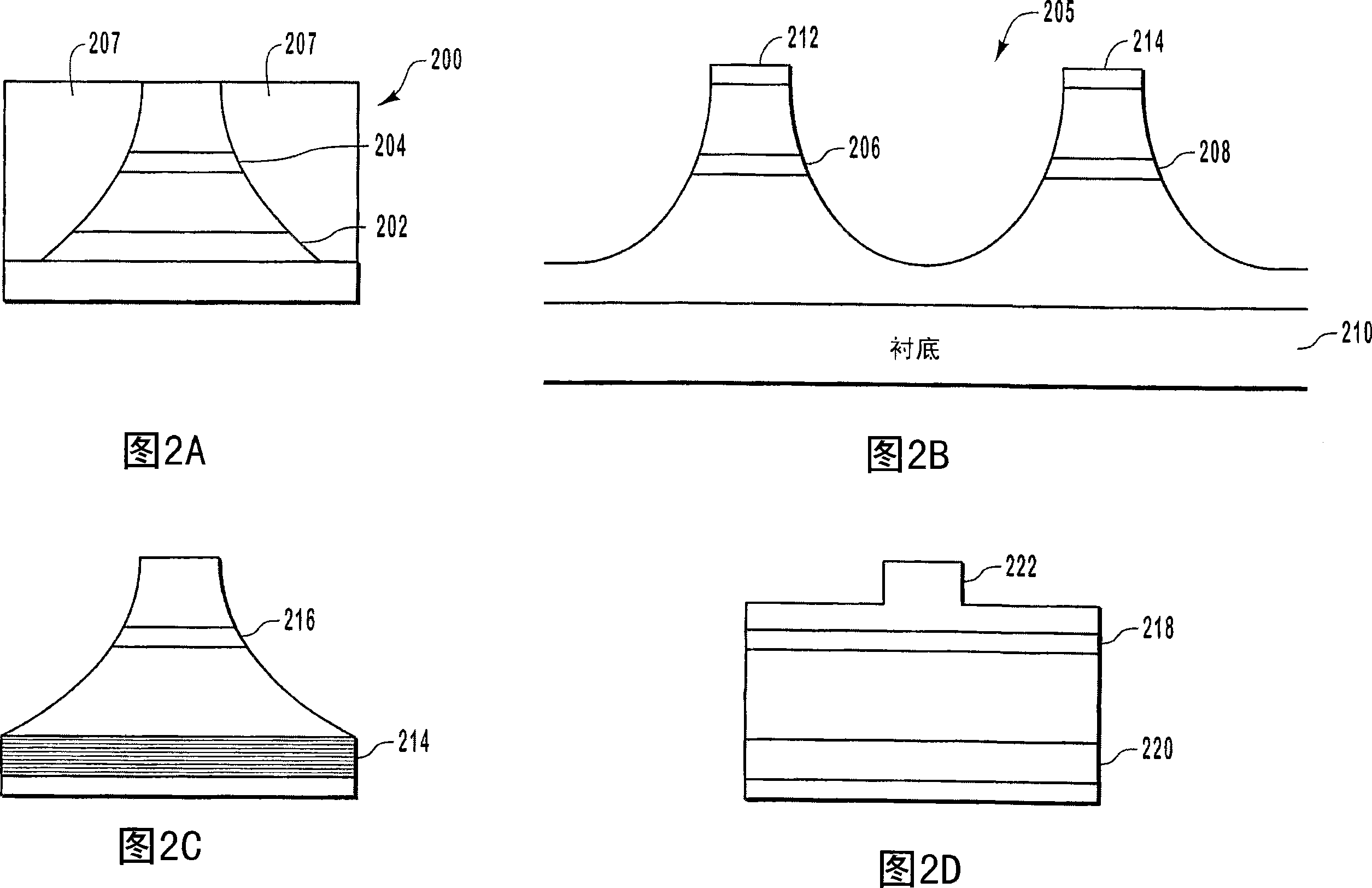
[0029] Embodiments of the present invention relate to extending the operating linear range of SOA. Expanding the linear range enables the SOA to linearly amplify optical signals over a wider range of optical power. The linear range of operation of the SOA is extended by providing optical feedback that linearizes the gain of the SOA as the optical output power increases. Another advantage of some embodiments of the present invention is the ability to increase the gain (gain expansion) as the optical output power increases, as opposed to gain ...


PUM


Abstract

Systems and methods for extending a linear range of a semiconductor optical amplifier (SOA). A feedback layer is included in an SOA. The optical mode of the SOA is distributed between the feedback layer and the active region. As output optical power increases, the mode confinement of the active region increases and the mode is drawn from the feedback layer into the active region. The increase in the mode confinement offsets a loss of material gain such that the linear range of the SOA is extended. In one embodiment, the modal gain increases an higher output optical powers.

Description

technical field [0001] The invention relates to the field of semiconductor optical amplifiers. More specifically, the present invention relates to semiconductor optical amplifiers with optical feedback. Background technique [0002] One of the ways to transfer information or data from one place to another is by using optical fibers in optical networks. A basic fiber optic network consists of transmitters, fibers and receivers. The transmitter uses a laser to convert the electrical signal into an optical signal. The optical signal or light generated by the laser is loaded into the optical fiber and transmitted through the optical network until it is received by the receiver. The receiver detects the optical signal generated by the laser and converts the detected optical signal into an electrical signal. Then, the data is extracted from the electrical signal. [0003] When optical signals are transmitted in optical fibers, they are often attenuated due to various reasons....

Claims


Application Information

Patent Timeline
Patent Type & Authority Applications(China)
IPC IPC(8): H01S3/00
CPCH01S2301/173H01S5/50H01S2301/18H01S5/3211H01S5/34366H01S5/4031H01S5/2027H01S5/3216H01S5/227H01S5/34313H01S5/2231B82Y20/00
Inventor 理查德·P.·拉特维斯凯阿希什·K.·维尔马丹尼尔·A.·弗朗西斯
Owner FINISAR
Learn More