
External resonator-type wavelength tunable laser device

a laser device and external resonator technology, applied in semiconductor lasers, laser details, electrical equipment, etc., can solve the problems of increasing the number of laser elements arranged in parallel, increasing the loss of couplers, and increasing the need for inventory control

Inactive Publication Date: 2012-05-29
NEC CORP
View PDF15 Cites 0 Cited by
  • Summary
  • Abstract
  • Description
  • Claims
  • Application Information

AI Technical Summary

Benefits of technology

[0041]An object of the present invention is to provide an external resonator-type wavelength tunable laser device that can solve at least one of the above-described problems. An example of a specific object is to provide an external resonator-type wavelength tunable laser device that can properly fulfill a wavelength tuning function even with the use of a planar wavelength tunable reflector involving a considerable level of residual reflection. Another specific object is to provide a semiconductor optical amplifier serving as a component of the wavelength tunable laser device and corresponding to a semiconductor gain medium, in order to provide the wavelength tunable laser device.

Problems solved by technology

For example, 100 channels require the respective, 100 types of laser devices, resulting in an increase in the need for inventory control and an increase in inventory costs.
Thus, an increase in the number of laser elements arranged in parallel correspondingly increases the loss of the coupler.
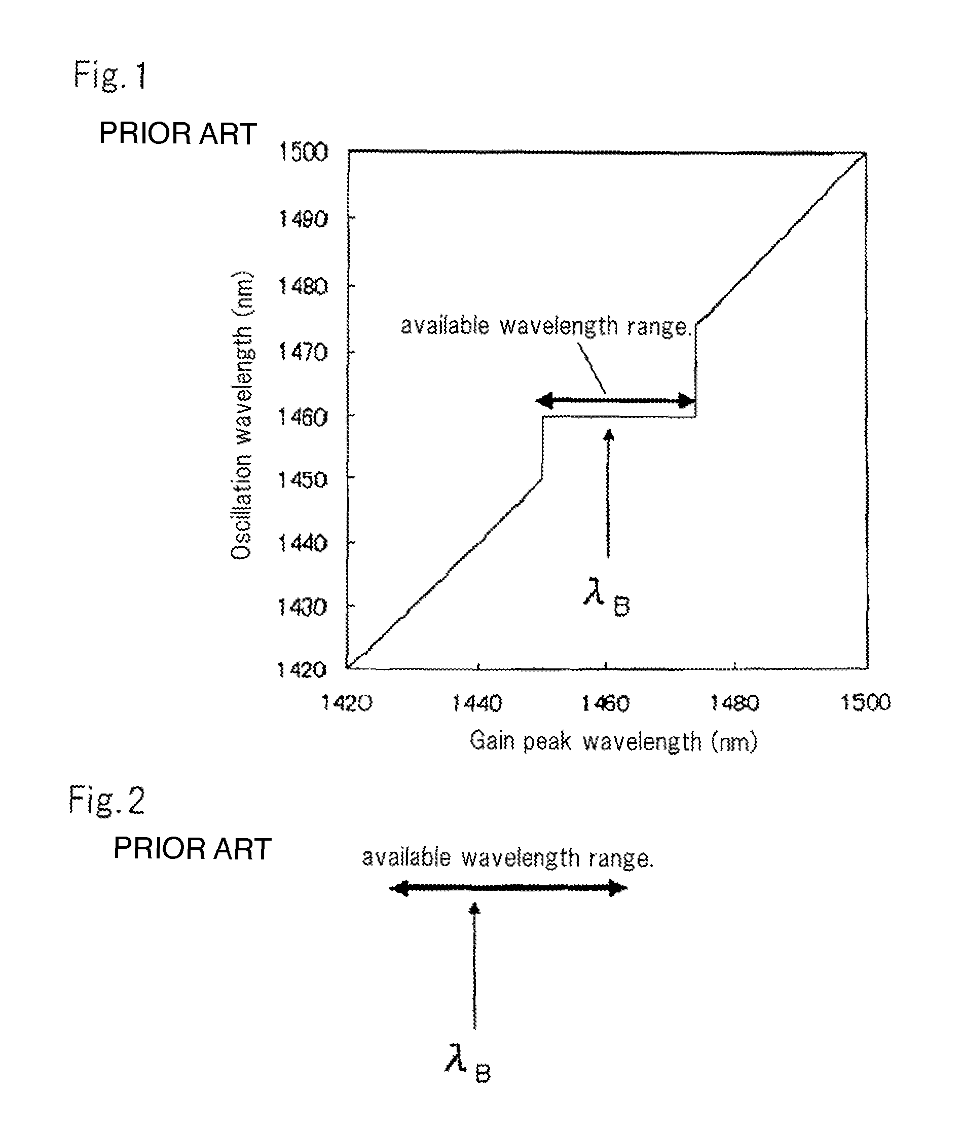
However, it has been found that when a planar wavelength tunable reflector is used to construct an external resonator-type wavelength tunable laser device in an attempt to obtain wavelength tunable characteristics, the laser device may disadvantageously oscillate at a wavelength that is different from the reflection spectral peak of the wavelength tunable reflector used.
However, this is disadvantageous to the wavelength tunable laser device.
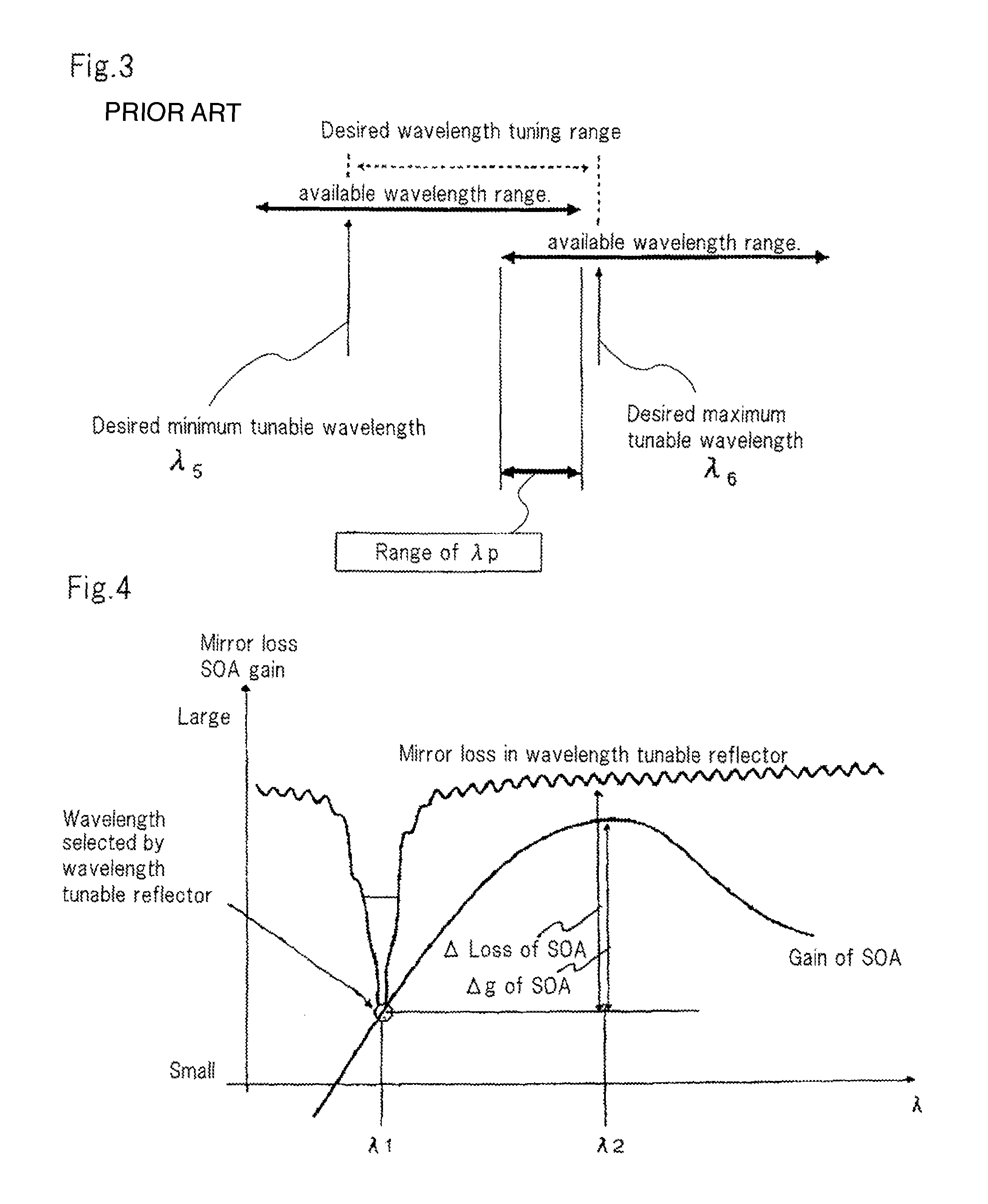
Thus, the wavelength tunable laser device with a wavelength tunable range of 30 nm to 35 nm or more fails to offer the possible range of gain peak wavelength λp of the semiconductor optical amplifier.
That is, the desired wavelength tunable range of the wavelength tunable laser device cannot be achieved.
It is thus very difficult to provide a wavelength tunable laser device with the desired wavelength tunable range based on the control only of gain peak wavelength λp of the semiconductor optical amplifier.
This problem is particularly significant when the wavelength tunable range of the wavelength tunable laser device is set to be equal to or wider than the range of about 30 nm to 35 nm, generally corresponding to a full band operation in one communication wavelength band.
However, in the planar reflection structure, setting ΔR to at least 20 dB is very difficult.

Method used


Image

  • External resonator-type wavelength tunable laser device
  • External resonator-type wavelength tunable laser device
  • External resonator-type wavelength tunable laser device

Examples


first example

[0166]A first example will be described below with reference to the drawings.

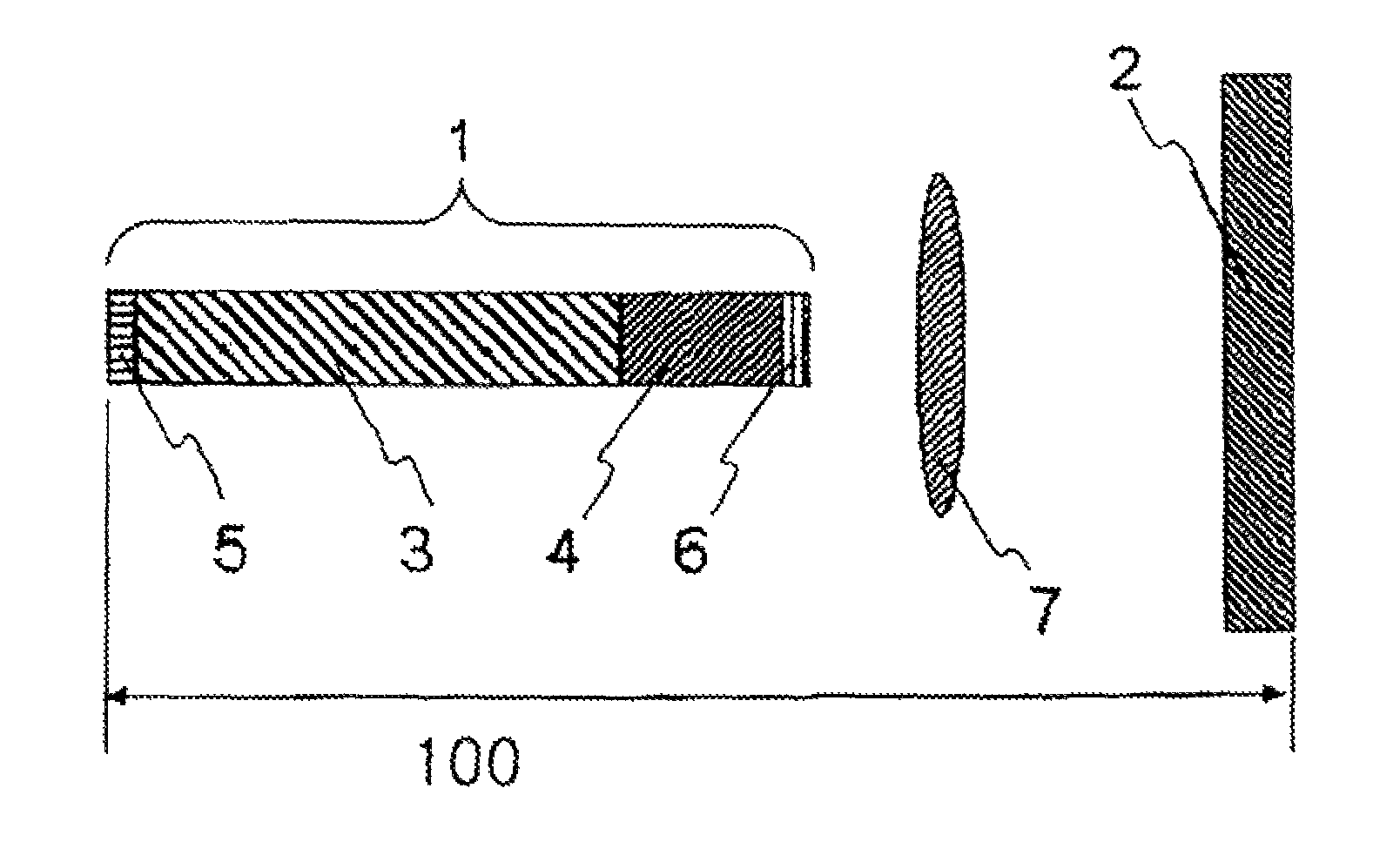
[0167]FIG. 13 is a diagram showing the configuration of an external resonator-type wavelength tunable laser device corresponding to the first example. In FIG. 13, the same components as those described above are denoted by the same reference numerals.

[0168]The external resonator-type wavelength tunable laser device according to the first example comprises semiconductor element 1 including semiconductor optical amplifier 3, collimating lens 7, planar wavelength tunable filter 8, and wavelength tunable reflection mirror 12 with an operation range corresponding to the vicinity of the C band (between 1,530 nm and 1,570 nm). The reflectance difference ΔR of wavelength tunable reflection mirror 12 is 8 dB.

[0169]Semiconductor element 1 includes circuit forming semiconductor optical amplifier 3 and a circuit used as phase adjustment region 4; the circuits are monolithically integrated. This integration was carried ...

second example

[0182]A second example will be described below with reference to the drawings.

[0183]The configuration of an external resonator-type wavelength tunable laser device according to the second example is the same as that according to the first example (FIG. 13).

[0184]The external resonator-type wavelength tunable laser device according to the present example comprises semiconductor element 1 including semiconductor optical amplifier 3, collimating lens 7, planar wavelength tunable filter 8, and wavelength tunable reflection mirror 12 with an operation range that corresponds to the vicinity of the C band (between 1,530 nm and 1,570 nm). The reflectance difference ΔR of wavelength tunable reflection mirror 12 is 8 dB.

[0185]Semiconductor element 1 includes circuit forming semiconductor optical amplifier 3 and a circuit used as phase adjustment region 4; the circuits are monolithically integrated. This integration was carried out using the butt joint technique.

[0186]First, an MQW structure u...

third example

[0198]A third example will be described below with reference to the drawings.

[0199]The configuration of an external resonator-type wavelength tunable laser device according to the third example is the same as that according to the first example (FIG. 13).

[0200]The external resonator-type wavelength tunable laser device according to the present example comprises semiconductor element 1 including semiconductor optical amplifier 3, collimating lens 7, wavelength tunable filter 8, and wavelength tunable reflection mirror 12 with an operation range of about 1,565 nm and 1,615 nm. ΔR of wavelength tunable reflection mirror 12 is 16 dB.

[0201]Semiconductor element 1 includes a circuit forming semiconductor optical amplifier 3 and a circuit used as phase adjustment region 4; the circuits are monolithically integrated. This integration was carried out using the butt joint technique.

[0202]First, an MQW structure used as semiconductor optical amplifier 3 is grown. Six MQW layers (each well was ...


PUM


Abstract

The present invention provides an external resonator-type wavelength tunable laser device that can properly fulfill a wavelength tuning function even with the use of a planar wavelength tunable reflector involving a considerable level of residual reflection. The external resonator-type wavelength tunable laser device includes a planar reflection structure enabling a reflection spectral peak wavelength to be varied and a semiconductor element as a semiconductor gain medium. The semiconductor gain medium is composed of a multiple quantum well in which product Γ·L of optical confinement constant Γ and semiconductor gain medium length L (μm) of a gain layer is at least 25 μm and at most 40 μm and in which gain peak wavelength λ0 (nm) observed during carrier injected with a maximum modal gain equal to an internal loss of the semiconductor gain medium is larger than −3·ΔR / 2+(λc+35) and smaller than (−(Γ·L) / 7+8)·ΔR+(−(Γ·L)+λc+45). Here, ΔR (dB) denotes a reflectance difference, and λc (nm) denotes a wavelength at a center of an operating wavelength range of the wavelength tunable laser device.

Description

[0001]The present application is the National Phase of PCT / JP2008 / 059446, filed May 22, 2008, which claims a priority based on Japanese Patent Laid-Open No. 2007-156214 filed on Jun. 13, 2007, and incorporates the entire disclosure thereof.TECHNICAL FIELD[0002]The present invention relates to an external resonator-type wavelength tunable laser device including a planar reflection structure enabling a reflection spectral peak wavelength to be varied, and a semiconductor optical amplifier contained in the wavelength tunable laser device to use as a semiconductor gain medium.BACKGROUND ART[0003]With the recent rapid prevalence of the Internet, there has been a demand for a further increase in the capacity of communication traffic. To deal with this, efforts have been made, in the field of optical communication systems, to increase the number of available channels by improving the transmission rate per channel and by utilizing a wavelength division multiplexing (WDM) scheme.[0004]The WD...

Claims


Application Information

Patent Timeline
Patent Type & Authority Patents(United States)
IPC IPC(8): H01S3/13
CPCH01S5/141H01S5/02248H01S5/028H01S5/0287H01S5/1039H01S5/02325
Inventor SUDO, SHINYASATO, KENJIKUDO, KOJIMIZUTANI, KENJIDE MERLIER, JAN
Owner NEC CORP
Learn More