
Cell culture carrier

Inactive Publication Date: 2021-03-18
TECH UNIV ILMENAU
View PDF0 Cites 0 Cited by
  • Summary
  • Abstract
  • Description
  • Claims
  • Application Information

AI Technical Summary

Benefits of technology

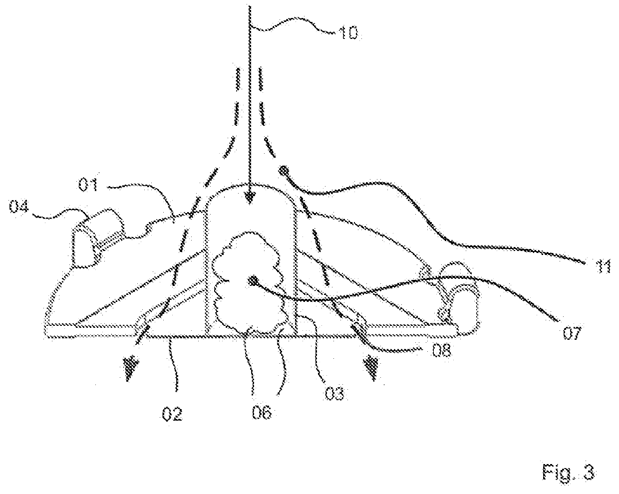
This patent describes a device that holds and supplies cells with nutrients. The device has a receiving cage that has porous walls that allow the nutrient solution to flow through. The cage has open ends, with the lower end closed by a membrane to hold the cells. The upper end can remain open for insertion of cells and visual observations. The main flow of nutrient solution flows through the cage, while a secondary flow flows along the outside of the cage, ensuring nutrient transport via the porous walls. This results in a high gradient of nutrients between the inside of the cage and the outside, allowing for better supply of the cells. The membrane is held securely and is made of the same porous material as the receiving cage, creating favorable pressure conditions. This device ensures safe and efficient supply of cells with nutrients.

Problems solved by technology

However, a high flow rate results in high shear forces in the cell clusters, and the sensitive tissue regions of said clusters cannot withstand these forces.
This ultimately results in the cell material being destroyed.
In the prior art, attempts are known to prevent the shear-force-related dissolution of a cell assembly by enclosing it in a receiving cage, but this does not solve the problem described.
Either a tightly closed cage prevents the desired high transport rate or a wide open cage cannot adequately protect the cell material.

Method used


Image

  • Cell culture carrier
  • Cell culture carrier

Examples


Embodiment Construction

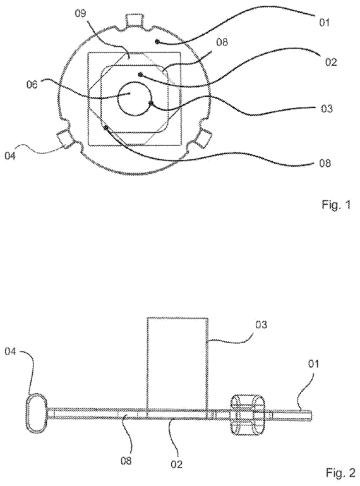
[0024]An exemplary embodiment of a cell culture carrier according to the invention is shown in FIGS. 1 to 3. The cell culture carrier has a carrier plate 01, a porous membrane 02 and a receiving cage 03.

[0025]The carrier plate 01 is designed here as a circular disk made of polycarbonate having a diameter of approx. 15 mm and has, on its outer edge, holding means 04 by means of which the entire cell culture carrier can be fastened in a housing (not shown). The membrane 02 is also produced as a structure made of polycarbonate and is clamped at its edges in the carrier plate 01. A colonization surface 06 is provided in the center of the membrane 02, on which cell material 07 can be deposited. The membrane is porous at least in the region of the colonization surface 06, such that a nutrient solution can flow through the pores.

[0026]The cylindrical receiving cage 03 stands up on the membrane 02 in the region of the colonization surface 06 and is fastened to said membrane. In other config...


PUM


Abstract

The invention relates to a cell culture carrier for cultivating biological cell material (07). The cell culture carrier comprises: a carrier plate (01); a membrane (02), which is supported by the carrier plate (01) and provides a colonization surface (06) for the cell material (07), the colonization surface (06) being permeable for a main flow (10) of a nutrient solution; and a holding cage (03), which is covered by the membrane (02) at an end and into which the cell material (07) can be introduced and through which the main flow (10) can flow. The carrier plate (01) provides a plurality of flow openings (08), which are positioned outside of the holding cage (03) in peripheral distribution and which allow a secondary flow (11) of the nutrient solution, the flow velocity of which secondary flow is greater than the flow velocity of the main flow (10) of the nutrient solution that flows through the holding cage (03) and the colonization surface (06). The invention further relates to a cell culture carrier assembly having a cell culture carrier of this type in a housing, which provides a flow region for a nutrient solution.

Description

BACKGROUND OF THE INVENTION[0001]The invention relates to a cell culture carrier for cultivating biological cell material. The cell culture carrier has a carrier plate, which is preferably adapted to external units, in which a large number of such cell culture carriers are usually combined and supplied with the media required for cell cultivation. The cell culture carrier also has a porous membrane which is carried by the carrier plate and is preferably designed as a structured molded body. The membrane is permeable to a main flow of a nutrient solution and provides a colonization surface for the cell material to be cultivated. Furthermore, the cell culture carrier comprises a receiving cage or a comparable cavity into which the cell material can be introduced. The receiving cage is arranged on the membrane, inserted therein or formed in one piece therewith, such that an end face of the receiving cage is covered by the membrane in order to hold the cell material in the cage. The mai...

Claims


Application Information

Patent Timeline
IPC IPC(8): C12M1/12
CPCC12M25/04C12M23/12C12M29/10
Inventor SCHOBER, ANDREASWEISE, FRANKHAMPL, JOERG
Owner TECH UNIV ILMENAU
Learn More