
Pitch control assembly for an aircraft-bladed rotor

Active Publication Date: 2021-03-11
PRATT & WHITNEY CANADA CORP
View PDF3 Cites 2 Cited by
  • Summary
  • Abstract
  • Description
  • Claims
  • Application Information

AI Technical Summary

Benefits of technology

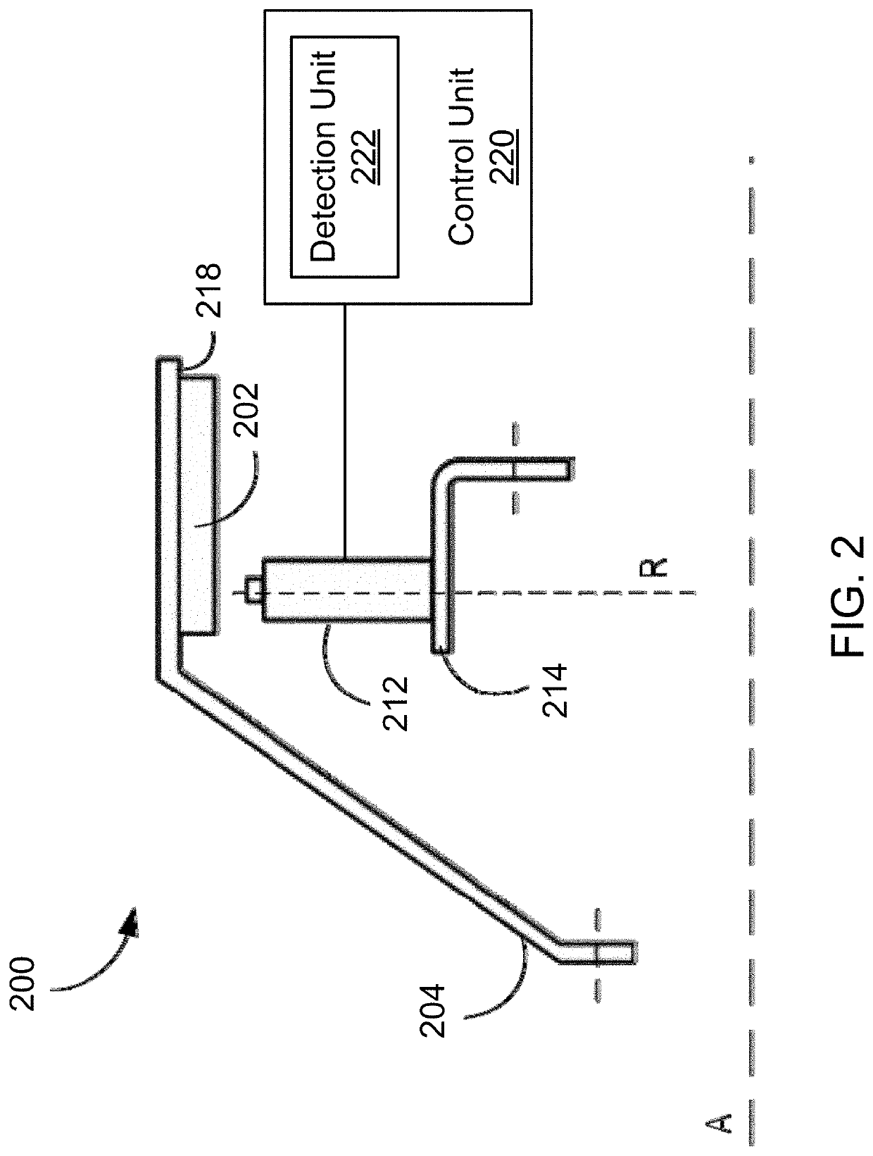
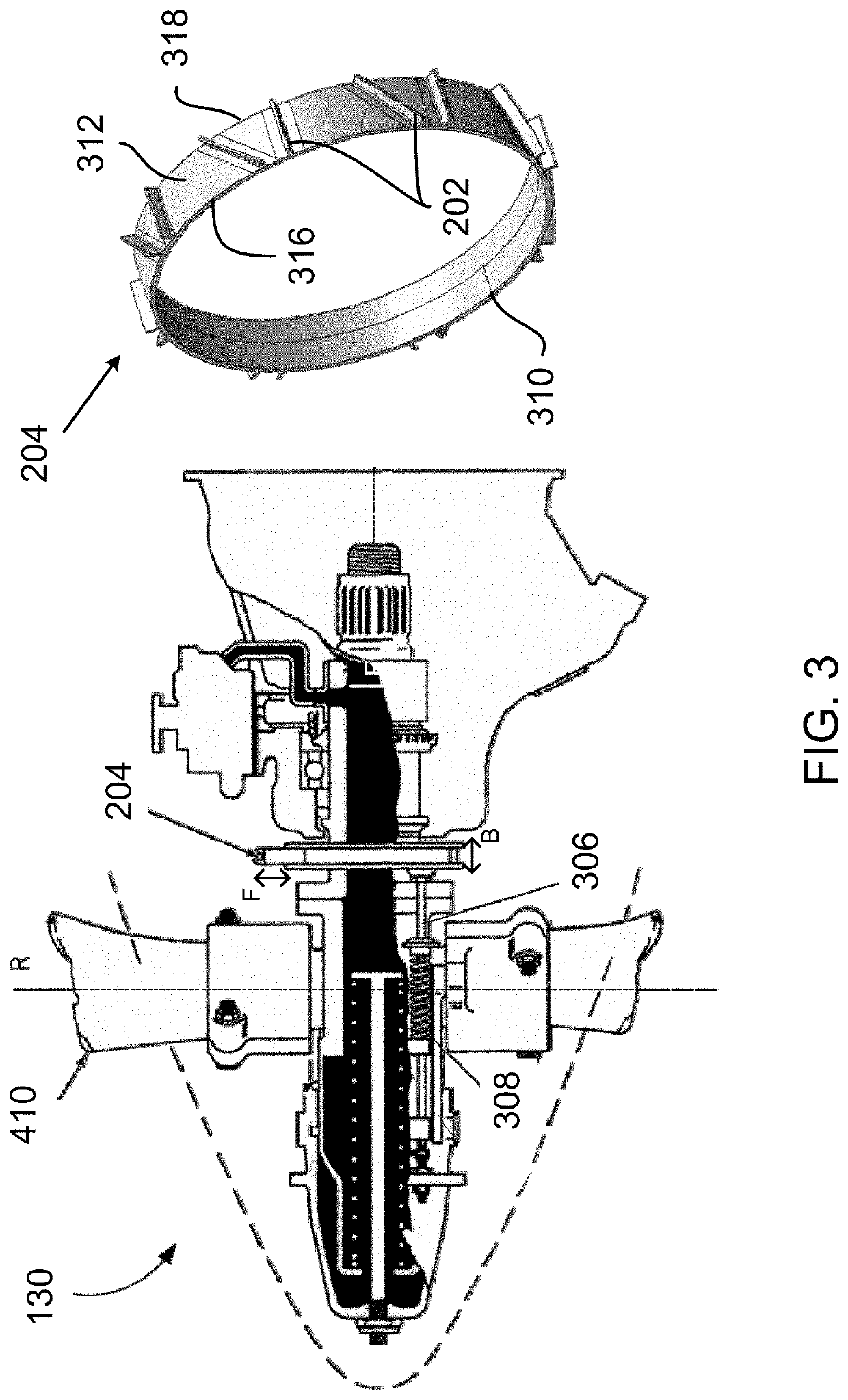
The patent describes a feedback device and method for controlling a pitch for an aircraft-bladed rotor. The feedback device consists of a circular disk and position markers that are attached to the disk. The position markers extend from the root surface of the disk and are spaced around the disk. The markers have higher magnetic permeability at their ends. The feedback device is coupled to the rotor and rotates with it. Sensors are placed near the feedback device to detect the position markers as they pass by, and the sensor signals are processed to identify the blade pitch angle. This feedback helps control the pitch of the rotor blades. The technical effects of this invention are improved accuracy and efficiency in controlling the blade pitch angle of an aircraft-bladed rotor.

Problems solved by technology

Existing feedback devices are however vulnerable to a so-called “edge-effect” that leads to an increase in reading error as the sensor approaches the edges of the feedback device.

Method used


Image

  • Pitch control assembly for an aircraft-bladed rotor
  • Pitch control assembly for an aircraft-bladed rotor
  • Pitch control assembly for an aircraft-bladed rotor

Examples


Embodiment Construction

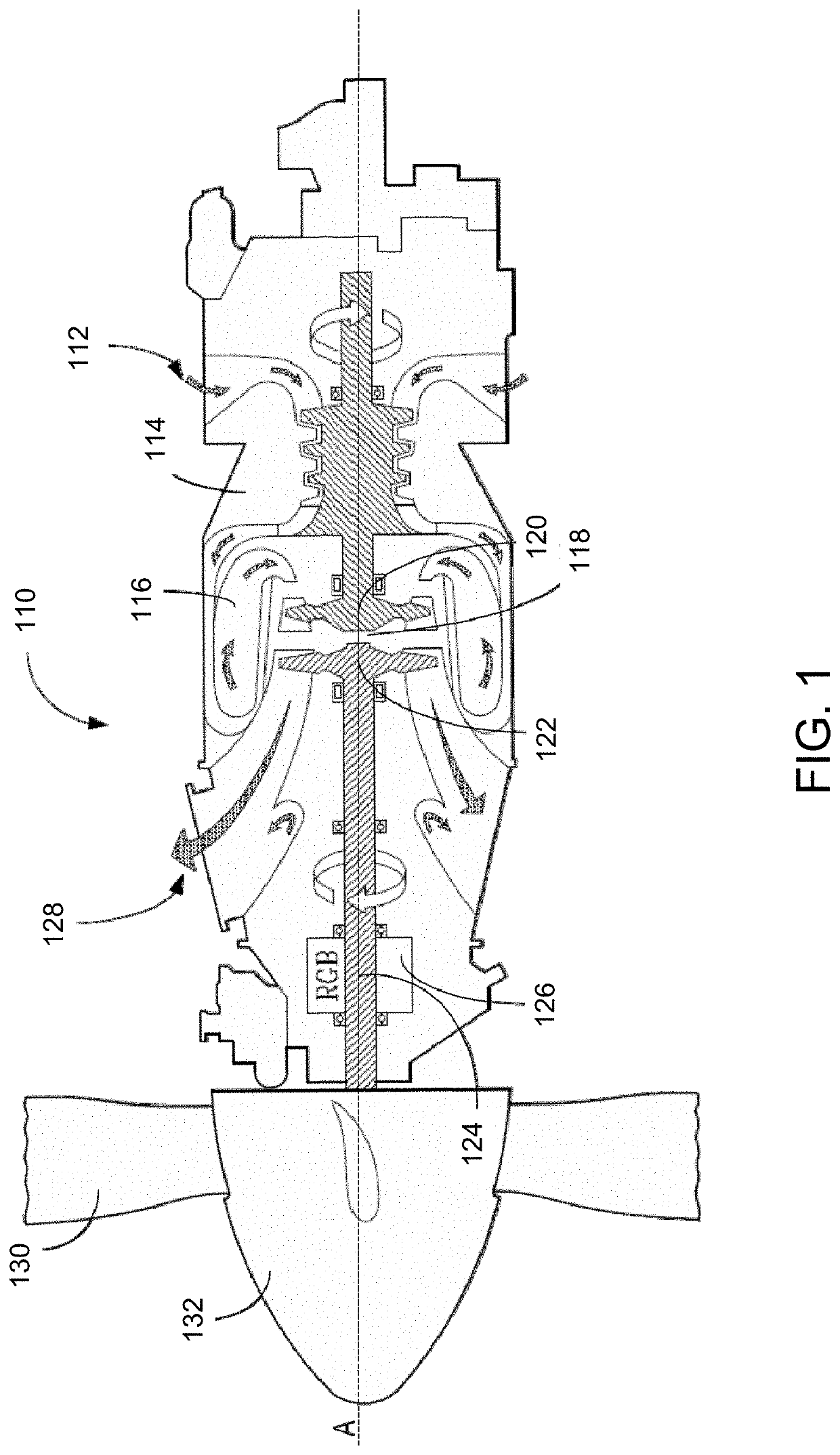
[0019]FIG. 1 depicts a gas turbine engine 110 of a type typically provided for use in subsonic flight. The engine 110 comprises an inlet 112 through which ambient air is propelled, a compressor section 114 for pressurizing the air, a combustor 116 in which the compressed air is mixed with fuel and ignited for generating an annular stream of hot combustion gases, and a turbine section 118 for extracting energy from the combustion gases.

[0020]The turbine section 118 comprises a compressor turbine 120, which drives the compressor assembly and accessories, and at least one power or free turbine 122, which is independent from the compressor turbine 120 and rotatingly drives a rotor shaft (also referred to herein as a propeller shaft or an output shaft) 124 about a propeller shaft axis ‘A’ through a reduction gearbox (RGB) 126. Rotation of the output shaft 124 is facilitated by one or more bearing assemblies, which can be disposed within the RGB 126 or at any other suitable location. Hot ...


PUM


Abstract

A feedback device for use in a gas turbine engine, and methods and systems for controlling a pitch for an aircraft-bladed rotor, are provided. The feedback device is composed of a circular disk and a plurality of position markers. The circular disk is coupled to rotate with a rotor of the gas turbine engine, to move along a longitudinal axis of the rotor, and has first and second opposing faces defining a root surface that extends between and circumscribes the first and second faces. The plurality of position markers extend radially from the root surface, are circumferentially spaced around the circular disk, and extending along the longitudinal axis from a first end portion to a second end portion. At least part of the first end portion and / or of the second end portion comprises a material having higher magnetic permeability than that of a remainder of the position markers.

Description

CROSS-REFERENCE TO RELATED APPLICATIONS[0001]This patent application claims the benefit of U.S. Provisional Patent Application 62 / 896,157, filed Sep. 5, 2019, and of U.S. Provisional Patent Application 62 / 896,163, filed Sep. 5, 2019.TECHNICAL FIELD[0002]The present disclosure relates generally to aircraft engines, and more specifically to pitch control systems for aircraft engines.BACKGROUND OF THE ART[0003]On featherable aircraft propeller systems, it is desirable to accurately measure the propeller blade pitch (or beta) angle to ensure that the blade angle is controlled according to the engine power set-point requested, such as in reverse and low pitch situations, also known as the beta operating region. For this purpose, some propeller feedback systems use a beta or feedback device, sometimes referred to as a phonic wheel, which rotates with the engine.[0004]The feedback device has multiple readable markers disposed on an outer surface thereof, and a sensor can be used to measure...

Claims


Application Information

Patent Timeline
IPC IPC(8): F02C9/22F02D29/02G01D5/12
CPCF02C9/22F02D29/02F02C7/32F05B2270/328G01D5/125F02C6/206F02C9/28B64C11/301F01D17/06F02C9/58F05D2270/02F05D2270/46F05D2270/821F05D2300/507G01B7/003G01D5/145G01P3/487G01P3/488F01D21/003F05D2260/70G01D5/2013G01D5/24438G01D5/2451B64D45/0005B63H2003/006B64C11/06B64D27/10F02D2041/281F02D2041/288F05D2220/323F01D7/00F01D17/20F05D2270/80F01D17/02F04D29/362B64C27/473B64C27/57B64C2027/4733
Inventor TOMESCU, DANA
Owner PRATT & WHITNEY CANADA CORP
Learn More