
Vehicle learning system, vehicle control device, and vehicle learning device

a learning system and vehicle technology, applied in the direction of electrical control, instruments, biological models, etc., can solve the problems of insufficient training data, complicated structure, and difficulty in verifying whether the neural network outputs a correct value, so as to improve accuracy, complicate the structure of mapping, and increase the load of calculation

Active Publication Date: 2021-02-25
TOYOTA JIDOSHA KK
View PDF3 Cites 4 Cited by
  • Summary
  • Abstract
  • Description
  • Claims
  • Application Information

AI Technical Summary

Benefits of technology

The patent text describes a method for improving the accuracy of output values by using a function approximator, such as a neural network, that takes into account the influence of certain variables on the output value. The method involves dividing the mapping used for calculating the output value into different pieces based on the value of a predetermined variable, which helps to improve accuracy while reducing the complexity of the mapping structure. The relationship between the predetermined variable and the mapping data is also updated based on the verification of the accuracy of the output value, which further improves the accuracy of the output value. Overall, this approach simplifies the mapping process and reduces the calculation load, while improving accuracy.

Problems solved by technology

However, before the neural network is mounted on a vehicle, sufficient training data may not always be obtained in various situations that may occur when the neural network is actually mounted on the vehicle.
When the sufficient training data cannot be obtained, it is difficult to verify whether the neural network outputs a correct value in various situations when the neural network is mounted on the vehicle.
However, the above manners complicate the structure of the mapping and may increase the load of the calculation requested for calculating the output value.

Method used


Image

  • Vehicle learning system, vehicle control device, and vehicle learning device
  • Vehicle learning system, vehicle control device, and vehicle learning device
  • Vehicle learning system, vehicle control device, and vehicle learning device

Examples


first embodiment

[0052]Hereinafter, a first embodiment of a vehicle learning system will be described with reference to drawings.

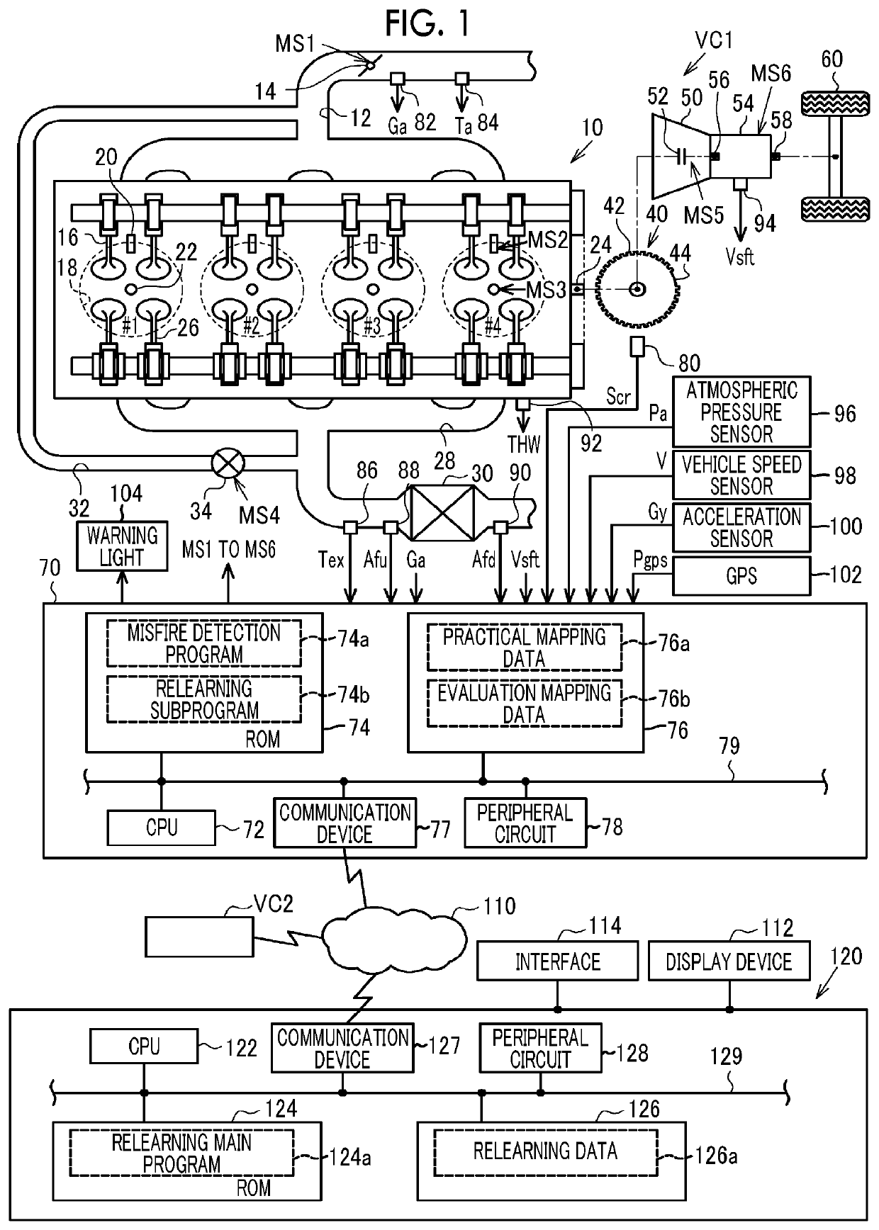
[0053]In an internal combustion engine 10 mounted on a vehicle VC1 shown in FIG. 1, a throttle valve 14 is provided in an intake passage 12. Air sucked from the intake passage 12 flows into respective combustion chambers 18 of cylinders #1 to #4 when intake valves 16 open. Fuel is injected into the combustion chamber 18 by a fuel injection valve 20. In the combustion chamber 18, an air-fuel mixture is supplied for combustion by spark discharge of an ignition device 22, and energy generated by the combustion is taken out as rotational energy of a crankshaft 24. The air-fuel mixture supplied for the combustion is discharged to an exhaust passage 28 as exhaust with an opening of an exhaust valve 26. A catalyst 30 having oxygen storage capacity is provided in the exhaust passage 28. The intake passage 12 and the exhaust passage 28 are connected by an EGR passage 32, and a flow...

second embodiment

[0121]Hereinafter, a second embodiment will be described with reference to drawings, focusing on differences from the first embodiment.

[0122]In the embodiment, low-rotation mapping data and high-rotation mapping data constitute the evaluation mapping data 76b and are used to evaluate the accuracy of misfire determination. FIG. 10 shows a procedure of the process of a selection process of the evaluation mapping data 76b. The process shown in FIG. 10 is realized by the CPU 72 repeatedly executing the misfire detection program 74a stored in the ROM 74 at a predetermined cycle, for example.

[0123]In a series of processes shown in FIG. 10, the CPU 72 determines whether the rotation speed NE is equal to or larger than a predetermined speed NEth (S124). When determination is made that the rotation speed NE is equal to or larger than the predetermined speed NEth (S124: YES), the CPU 72 selects the high-rotation mapping data among the evaluation mapping data 76b (S126). The high-rotation mapp...

third embodiment

[0130]Hereinafter, a third embodiment will be described with reference to drawings, focusing on differences from the first embodiment.

[0131]In the embodiment, for a variable that is not the input variables x(1) to x(26) to the mapping defined by the evaluation mapping data 76b, the variable is added to the input variable when the erroneous output rate is significant in a part of regions divided by the variable.

[0132]FIG. 13 shows a partial procedure of a process relating to the relearning of the evaluation mapping data 76b according to the embodiment. The process shown on the left side of FIG. 13 is realized by the CPU 72 executing the relearning subprogram 74b stored in the ROM 74 shown in FIG. 1. The process shown on the right side of FIG. 13 is realized by the CPU 122 executing the relearning main program 124a stored in the ROM 124. In the process shown in FIG. 13, the same step numbers are assigned to the process corresponding to the process shown in FIG. 6 for convenience.

[0133...


PUM


Abstract

A vehicle learning system includes a first execution device mounted on a vehicle, a second execution device outside the vehicle, and a storage device. The storage device stores mapping data including data, which is learned by machine learning and defines mapping that receives input data based on a detection value of an in-vehicle sensor and outputs an output value. The first execution device and the second execution device execute, in cooperation with each other, an acquisition process of acquiring input data, a calculation process of calculating an output value with the input data as an input of the mapping, and a relationship evaluation process of evaluating a relationship between a predetermined variable different from a variable corresponding to the output value and accuracy of the output value. The first execution device executes at least the acquisition process, and the second execution device executes at least the relationship evaluation process.

Description

INCORPORATION BY REFERENCE[0001]The disclosure of Japanese Patent Application No. 2019-152137 filed on Aug. 22, 2019 including the specification, drawings and abstract is incorporated herein by reference in its entirety.BACKGROUND1. Technical Field[0002]The present disclosure relates to a vehicle learning system, a vehicle control device, and a vehicle learning device.2. Description of Related Art[0003]For example, Japanese Unexamined Patent Application Publication No. 4-91348 (JP 4-91348 A) discloses a device provided with a neural network that receives a rotation fluctuation amount which is a change amount of rotation speed and outputs a value indicating whether a misfire occurs in each of a plurality of cylinders of an internal combustion engine.SUMMARY[0004]By the way, learning using training data in various situations is generally needed in order to enhance the reliability of a learned model learned by machine learning. However, before the neural network is mounted on a vehicle...

Claims


Application Information

Patent Timeline
Patent Type & Authority Applications(United States)
IPC IPC(8): B60W50/04B60W50/02G06N3/08
CPCB60W50/045B60W2050/0026G06N3/08B60W50/0205F02D41/1405F02D41/22F02D29/02F02D2200/0414F02D2200/703F02D2200/101F02D2200/1015F02D41/1497G01M15/11F02D2200/0804F02D41/266G06N5/046G06N20/00G06N3/042B60W2050/0062B60W2510/0638B60W2510/0676
Inventor HASHIMOTO, YOHSUKEKATAYAMA, AKIHIROOSHIRO, YUTASUGIE, KAZUKIOKA, NAOYA
Owner TOYOTA JIDOSHA KK
Learn More