
Detecting system of liquid leakage inside the duct and the method thereof

a detection system and liquid leakage technology, applied in lighting and heating apparatus, heating types, instruments, etc., can solve the problems of valve seat tilting or damage, valve leakage, and the amount of added liquid not being as expected, so as to prevent the possibility of adverse consequences

Inactive Publication Date: 2021-02-11
CHUNG YUAN CHRISTIAN UNIVERSITY +1
View PDF0 Cites 2 Cited by
  • Summary
  • Abstract
  • Description
  • Claims
  • Application Information

AI Technical Summary

Benefits of technology

The invention aims to provide a simple and low-cost method for detecting liquid leakage inside a duct, which is a common issue in industrial applications. The detection system consists of a duct, a detection component, and a signal processing component. The detection component is fixed to the duct wall and works by detecting the presence of liquid inside the duct. When liquid activates the detection component, it sends a signal to the signal processing component for further processing. This design allows for quick detection of leaks and efficient response by operators, and also facilitates connection to central control systems for emergency measures and preventive shutdowns.

Problems solved by technology

However, conventional hemispherical valves often cause tilting or damage of the valve seat and the valve stem due to excessive use.
And causing the hemisphere valve to leak, lead to the amount of added liquid is not as expected.
Slight, resulting in product quality is not up to standard.
In severe cases, food quality deterioration causes food safety hazards.
In addition, it was found that when a product abnormality occurs due to liquid leakage in the pipeline, often separated by more than a period of time, and the addition of liquid has affected a considerable number of products.
This method is not only labor-intensive, and it will cause great delays in the production line and equipment maintenance.
But the creator knows about the prior art, it was found that there is no set of standards or devices for in-line leak detection that can solve the above problems.

Method used


Image

  • Detecting system of liquid leakage inside the duct and the method thereof
  • Detecting system of liquid leakage inside the duct and the method thereof
  • Detecting system of liquid leakage inside the duct and the method thereof

Examples


first embodiment

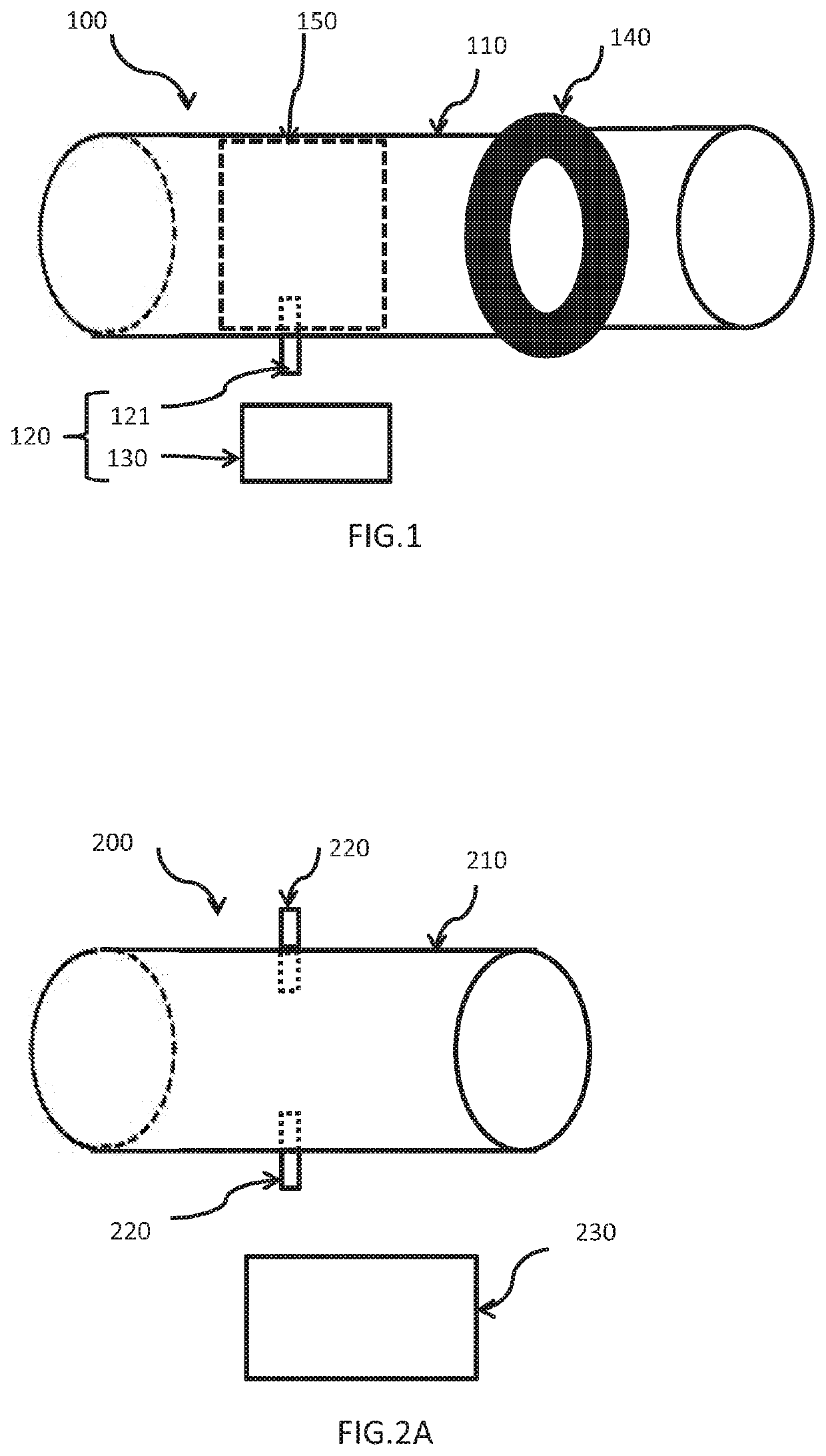
[0042]Referring to FIG. 1, a detecting system of liquid leakage inside the duct 100 is disclosed, which is used when the liquid is not transported inside the duct according to the present invention. The detecting system 100 comprises: a duct 110, a valve 140, a detecting module 120. The duct 110 is for conveying liquid, and the valve is located at a predetermined position of said duct 110 to control the flow of the liquid. Moreover, the detecting module 120 is located after the liquid outlet end of said valve 140 and inside said duct 110, wherein said valve 140 is closed to stop the delivery of liquid, said detecting module 120 starts detecting and generates a warning signal when the leakage of liquid occurs.

[0043]Furthermore, the detecting module 120 further includes at least one detecting device 121 and at least one signal processing device 130; wherein the detecting device 121 is activated when said valve 140 is closed to stop conveying liquid and a leakage of liquid is generated...

second embodiment

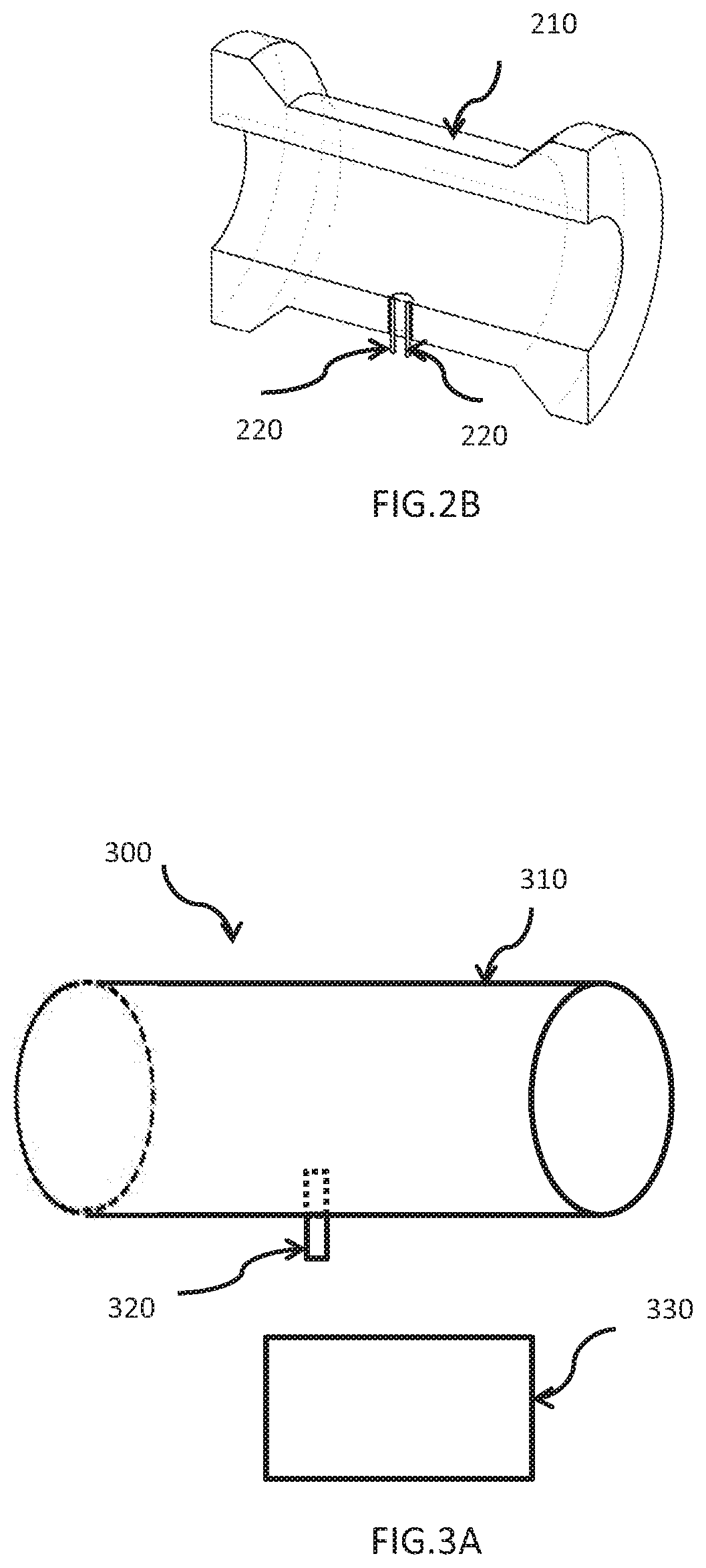
[0044]Referring to FIG. 2A, 2B, a detecting system of liquid leakage inside the duct 200 is disclosed, which is used when the liquid is not transported inside the duct according to the present invention. The detecting system 200 comprises: a duct 210, an optical detecting device 220, a signal processing device 230. The optical detecting device 220 is penetrated and fixed to the wall inside the duct 210. Wherein, the optical detecting device 220 is a light blocking type. Wherein, the optical detecting device 220 is used for starting detection when the liquid is not delivered inside the duct 210. When the liquid activates the optical detecting device 220, the optical detecting device 220 sends a signal to the signal processing device 230 for subsequent processing.

[0045]The optical detecting device 220 described above is a group of light emitting elements and light receiving elements. There is a gap between the light-emitting element and the light-receiving element. If there is no obje...

third embodiment

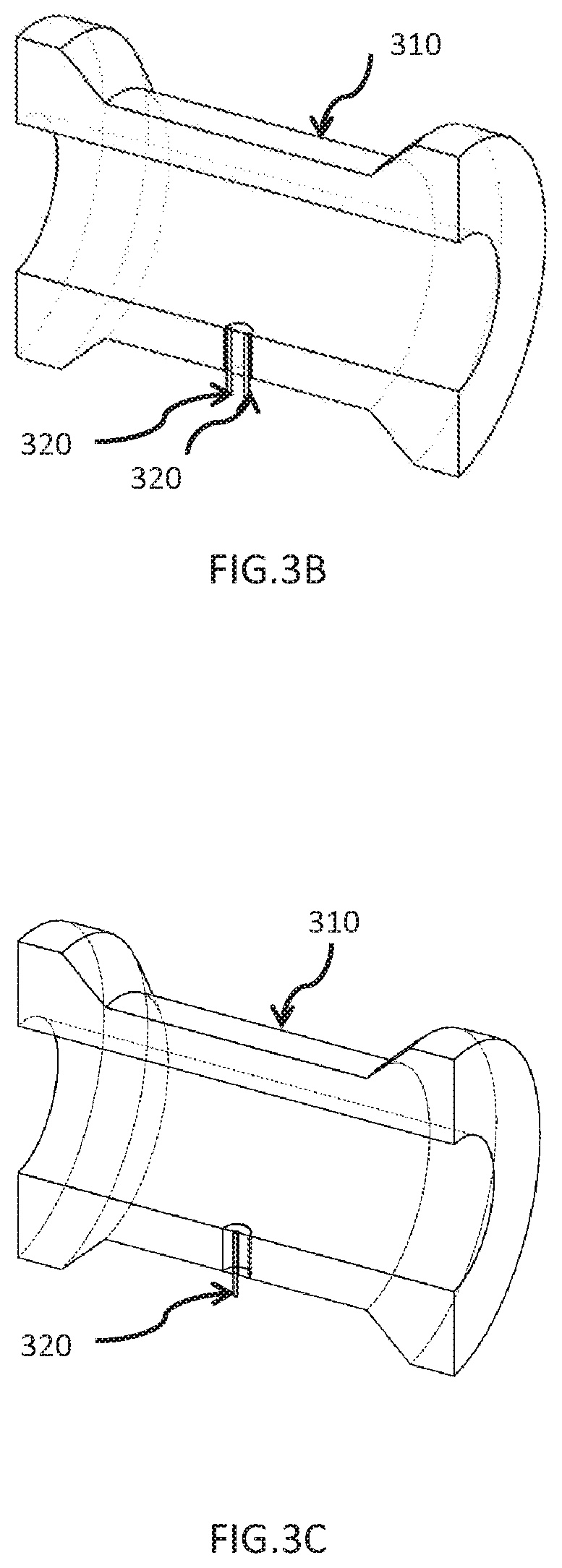
[0046]Referring to FIG. 3A, 3B, a detecting system of liquid leakage inside the duct 300 is disclosed, which is used when the liquid is not transported inside the duct according to the present invention. The detecting system 300 comprises: a duct 310, a capacitive detecting device 320, a signal processing device 330. The capacitive detecting device 320 is penetrated and fixed to the wall inside the duct 310. Wherein, the capacitive detecting device 320 is a light blocking type. Wherein, the capacitive detection component 320 is used for starting detection when the liquid is not delivered inside the duct 310. When the liquid activates the capacitive detecting device 320, the capacitive detecting device 320 sends a signal to the signal processing device 330 for subsequent processing.

[0047]Referring to FIGS. 3B and 3C, the capacitive detecting device 320 described above is a system may be a two-point metal probe or single-point metal probes and metal pipes, wherein, the metal pipe is u...


PUM


Abstract

The present invention provides a detecting system and method of liquid leakage inside the duct, which is used when the liquid is not transported inside the duct. The detecting system comprises: a duct, a detecting device, a signal processing device. The detecting device is fixed to the wall inside the duct. And the detecting device is used for starting detection when the liquid is not delivered inside the duct. When the liquid activates the detecting device, the detecting device sends a signal to the signal processing device for subsequent processing.

Description

FIELD OF THE INVENTION[0001]The present invention relates to a detecting system and method of liquid leakage inside the duct, especially to a detecting system and method of liquid leakage inside the duct designed particularly for when liquid is not transported inside the duct.BACKGROUND OF THE INVENTION[0002]The design is simple, economical and efficient. When the sensor detects the leakage, the signal would be transmitted to the operator and the operator could take emergency measures immediately. The device could also be connect with PLC control center. The central control system could shut down the power to stop the operation and prevent the possibilities of adverse consequences.[0003]With the advancement of industrial technology, the quality of products is continuously improved, and the production equipment used must be required to achieve a certain appropriate rate and improve its performance in the process; for example, in the production process. The reliability of the liquid d...

Claims


Application Information

Patent Timeline
IPC IPC(8): F24F11/36F24F13/02F24F11/84
CPCF24F11/36F24F2140/30F24F11/84F24F13/0236F17D5/06G01M3/2876
Inventor FAN, YI-HUAKAO, HSIANG
Owner CHUNG YUAN CHRISTIAN UNIVERSITY
Learn More