
Strontium tetraborate as optical coating material

a technology of strontium tetraborate and optical coating, which is applied in the direction of optical elements, semiconductor/solid-state device testing/measurement, instruments, etc., can solve the problems of inability to stabilize mgf/sub>2 /sub>coatings, which are necessarily amorphous, and the spectral range of duv (200 nm to 280 nm), so as to facilitate the generation of improved frequency conversion crystals, slow or stop

Active Publication Date: 2020-11-12
KLA TENCOR TECH CORP
View PDF0 Cites 0 Cited by
  • Summary
  • Abstract
  • Description
  • Claims
  • Application Information

AI Technical Summary

Benefits of technology

The present invention relates to a coating material for optical components in semiconductor inspection and metrology systems. The coating material is strontium tetraborate (SrB4O7) which has unique properties that make it suitable for use in extreme conditions. The optical properties of SrB4O7 include high optical damage threshold, high refractive indices, and high microhardness. The high optical damage threshold allows for optical components to withstand the high power levels and photon energy of DUV and VUV lasers. The high refractive indices and low reflectance of DUV and VUV light make it ideal for use in optical systems. The high mechanical hardness of SrB4O7 also allows for enhanced protection of the underlying optical materials. The optical coating layer can be adjusted for reflectivity and can be formed on a variety of optical components. The use of this coating material increases the effective lifetime of optical components, reduces the operating costs of the system, and improves the performance of the system.

Problems solved by technology

Optical coatings in the DUV (˜200 nm to 280 nm) and VUV (˜100 nm to 200 nm) spectral ranges are challenging.
However, MgF2 coatings, which are necessarily amorphous, may not be stable as time goes by.

Method used


Image

  • Strontium tetraborate as optical coating material
  • Strontium tetraborate as optical coating material
  • Strontium tetraborate as optical coating material

Examples


Embodiment Construction

[0026]Although the claimed subject matter will be described in terms of certain embodiments, other embodiments, including embodiments that do not provide all of the benefits and features set forth herein, are also within the scope of this disclosure. Various structural, logical, process step, and electronic changes may be made without departing from the scope of the disclosure. Accordingly, the scope of the disclosure is defined only by reference to the appended claims.

[0027]The following description is presented to enable one of ordinary skill in the art to make and use the disclosure as provided in the context of a particular application and its requirements. As used herein, directional terms such as “top,”“bottom,”“over,”“under,”“upper,”“upward,”“lower,”“down,” and “downward” are intended to provide relative positions for purposes of description and are not intended to designate an absolute frame of reference. Various modifications to the preferred embodiment will be apparent to ...


PUM

PropertyMeasurementUnit
Timeaaaaaaaaaa
Thicknessaaaaaaaaaa
Thicknessaaaaaaaaaa

Abstract

Strontium tetraborate is used as an optical coating material for optical components utilized in semiconductor inspection and metrology systems to take advantage of its high refractive indices, high optical damage threshold and high microhardness in comparison to conventional optical materials. At least one layer of strontium tetraborate is formed on the light receiving surface of an optical component's substrate such that its thickness serves to increase or decrease the reflectance of the optical component. One or multiple additional coating layers may be placed on top of or below the strontium tetraborate layer, with the additional coating layers consisting of conventional optical materials. The thicknesses of the additional layers may be selected to achieve a desired reflectance of the optical component at specific wavelengths. The coated optical component is used in an illumination source or optical system utilized in a semiconductor inspection system, a metrology system or a lithography system.

Description

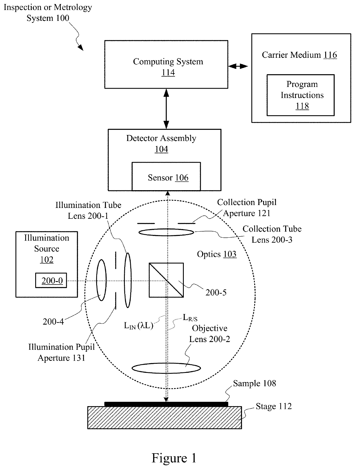
RELATED APPLICATIONS[0001]This application claims priority from U.S. Provisional Patent Application No. 62 / 845,496, entitled “STRONTIUM TETRABORATE AS OPTICAL COATING MATERIAL”, which was filed on May 9, 2019, and is incorporated by reference herein. This application also claims priority from U.S. Provisional Patent Application No. 62 / 913,643, entitled “STRONTIUM TETRABORATE AS OPTICAL COATING MATERIAL”, which was filed on Oct. 10, 2019, and is incorporated by reference herein.FIELD OF THE DISCLOSURE[0002]The present disclosure relates generally to systems of a type suitable for use in semiconductor manufacturing (e.g., to inspect and / or measure photomasks, reticles, and semiconductor wafers). In particular, the disclosure relates to optical coating materials for optical components (e.g., mirrors, lenses, prisms and lasers) implemented in metrology and inspection systems that utilize infrared, visible light, deep ultraviolet (DUV) and vacuum ultraviolet (VUV) radiation.BACKGROUND OF...

Claims


Application Information

Patent Timeline
IPC IPC(8): G01N21/95G02F1/35G02F1/355G02B21/00G02B21/16G02B5/28G02B21/06G01N21/33
CPCG02B21/06G02B5/285G02B21/16H01L22/12G02F1/353G02B21/0016G01N21/33G01N2201/06113G02F1/3551G01N21/9501C23C14/067C23C14/0694C23C14/10C23C14/30G02B1/115G02B1/18G02B5/283G01N2021/95676C09D1/00G01N2201/068G01B11/24G01N21/8806B05D5/06C09D5/004G01N21/55
Inventor CHUANG, YUNG-HO ALEXXIAO-LI, YINYINGLOGINOVA, ELENAFIELDEN, JOHN
Owner KLA TENCOR TECH CORP
Learn More