
Catalyst deterioration recovery device and catalyst deterioration recovery method

a recovery device and catalyst technology, applied in the direction of solid electrolyte fuel cells, fuel cells, electrical equipment, etc., can solve the problems of fuel gas containing oxygen and deteriorating an electrolyte membrane, and achieve the effect of suppressing the deterioration of an electrolyte membran

Active Publication Date: 2020-06-11
NISSAN MOTOR CO LTD
View PDF0 Cites 4 Cited by
  • Summary
  • Abstract
  • Description
  • Claims
  • Application Information

AI Technical Summary

Benefits of technology

The patent text describes an invention that allows for the recovery of catalysts in a fuel cell system without causing damage to the membrane electrode assembly. The invention includes a recovery control unit that supplies oxygen to the anode catalyst to remove carbon monoxide and recover its performance. The technical effect of this invention is to restore the performance of the fuel cell system quickly and efficiently.

Problems solved by technology

However, there is a possibility that the catalyst recovery process performed by causing fuel gas to contain oxygen as described above deteriorates an electrolyte membrane due to reaction heat generated by the reaction of hydrogen and oxygen on the electrode catalyst.

Method used


Image

  • Catalyst deterioration recovery device and catalyst deterioration recovery method
  • Catalyst deterioration recovery device and catalyst deterioration recovery method
  • Catalyst deterioration recovery device and catalyst deterioration recovery method

Examples


first embodiment

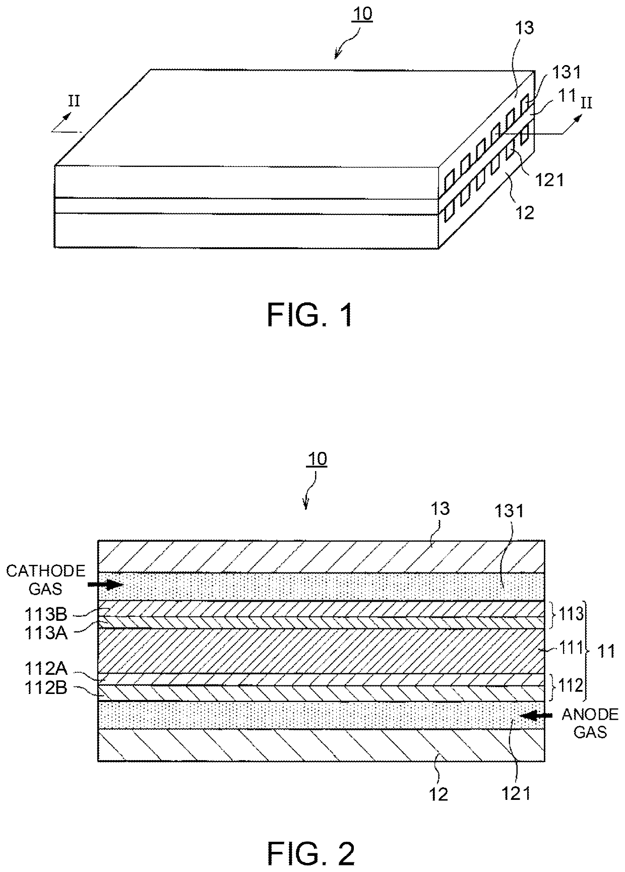
[0024]FIGS. 1 and 2 are diagrams explaining the configuration of a fuel cell 10 according to an embodiment of the present invention. FIG. 1 is a perspective diagram illustrating the fuel cell 10 and FIG. 2 is a cross-sectional diagram viewed from the II-II line of the fuel cell 10 illustrated in FIG. 1.

[0025]The fuel cell 10 includes a membrane electrode assembly (MEA) 11 and anode and cathode separators 12 and 13 that are arranged to sandwich the MEA 11 therebetween.

[0026]The MEA 11 is configured to include an electrolyte membrane 111, an anode electrode 112, and a cathode electrode 113. The MEA 11 includes the anode electrode 112 on one side and the cathode electrode 113 on the other side of the electrolyte membrane 111.

[0027]The electrolyte membrane 111 is an ion exchange membrane having proton conductivity formed of fluorinated resin. The electrolyte membrane 111 shows good electrical conductivity in a wet / dry state.

[0028]The anode electrode 112 includes a catalyst layer 112A an...

second embodiment

[0118]The present embodiment is similar to the first embodiment in light of the basic thinking of the catalyst recovery process of cross-leaking oxygen toward the anode, but is different from the first embodiment in light of a process for cross-leaking oxygen.

[0119]The first embodiment increases the partial pressure difference dP of oxygen so as to increase the permeation flux F of oxygen. On the contrary, the present embodiment increases the permeation coefficient k of oxygen so as to increase the permeation flux F of oxygen. Hereinafter, a method of increasing the permeation coefficient k will be explained.

[0120]FIG. 12 illustrates a relationship between the oxygen permeation coefficient of the electrolyte membrane 111 and the temperature and water content of the electrolyte membrane 111. As illustrated in FIG. 12, the electrolyte membrane 111 has a characteristic that the oxygen permeation coefficient grows larger as the temperature becomes higher. Moreover, as illustrated in FIG...


PUM

PropertyMeasurementUnit
oxidation reaction rateaaaaaaaaaa
adsorptionaaaaaaaaaa

Abstract

A catalyst deterioration recovery device in a fuel cell system that includes a fuel cell including a membrane electrode assembly configured to include an electrolyte membrane and anode and cathode catalysts between which the electrolyte membrane is sandwiched from both sides and anode and cathode separators respectively including an anode gas flow channel and a cathode gas flow channel, the membrane electrode assembly being sandwiched between the anode and cathode separators. The catalyst deterioration recovery device recovers performance decreased by adsorption of carbon monoxide to the anode catalyst. The catalyst deterioration recovery device includes a recovery control unit configured to supply at least a part of oxygen to be supplied to the cathode gas flow channel to the anode catalyst via the electrolyte membrane.

Description

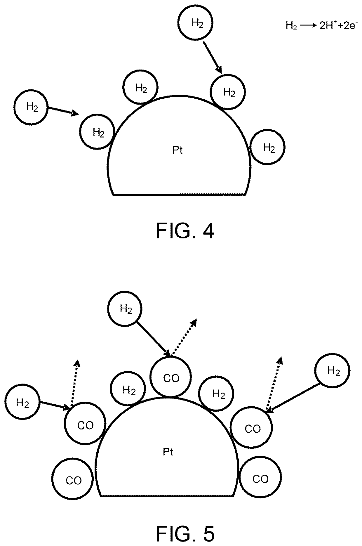
TECHNICAL FIELD[0001]The present invention relates to a deterioration recovery device and a deterioration recovery method of an electrode used for a fuel cell system.BACKGROUND ART[0002]In a fuel cell system that supplies fuel gas containing hydrogen to a fuel electrode and supplies oxygen-containing gas to an oxygen electrode to perform power generation, an electrode reaction is blocked and thus power performance is decreased when a phenomenon, in which carbon monoxide (hereinafter, also called “CO”) adsorbs onto an electrode catalyst of the fuel electrode, so-called CO poisoning occurs.[0003]As a process (hereinafter, also called “catalyst recovery process”) for resolving the CO poisoning, Japanese Patent Application Laid-Open No. 2005-25985 and Japanese Patent No. 5008319 disclose a method of causing fuel gas to be supplied to a fuel electrode to contain oxygen and thus oxidizing CO to detach it from an electrode catalyst. Moreover, Japanese Patent No. 3536645, Japanese Patent No...

Claims


Application Information

Patent Timeline
Patent Type & Authority Applications(United States)
IPC IPC(8): H01M8/1004H01M8/04223H01M8/04746H01M8/04664H01M8/04701H01M8/04828H01M8/0267H01M8/0258
CPCH01M8/1004H01M8/04753H01M8/04223H01M8/0267H01M8/0258H01M8/04723H01M8/04664H01M8/0485H01M8/10Y02E60/50H01M8/04701
Inventor IDEN, HIROSHIONO, YOSHITAKATAKAICHI, SATOSHI
Owner NISSAN MOTOR CO LTD
Learn More