
Method and system for conveying articles and an apparatus for doing the same

a technology of conveyors and articles, applied in the direction of conveyor parts, sorting, storage devices, etc., can solve the problems of occupying valuable floor space, reducing the efficiency of conveyors, and reducing so as to facilitate the efficiency of tire loading, unloading and/or storage, and reduce the level of inventory

Active Publication Date: 2020-05-07
MULTIELEVATOR
View PDF7 Cites 13 Cited by
  • Summary
  • Abstract
  • Description
  • Claims
  • Application Information

AI Technical Summary

Benefits of technology

The present invention provides a tire sorting apparatus that can read information from a tire identifier, such as a barcode, without damaging the tire. This allows for the reliable identification and sorting of tires, and the unloading of conveyed articles from a rack. The method involves using a computer-controlled vision system to read the identification information on the conveyed articles, and a robot to remove the tires from the conveyor belt and place them in a suitable location. This invention improves the efficiency and accuracy of tire inspection and sorting processes.

Problems solved by technology

Rubber-topped belts are not so susceptible to wear, but the slippery mold-release material used to ease ejection of the tires from the presses coats the rubber conveying surface of the belt, which then loses its effectiveness as a high-friction surface.
Such shallow inclines have a large footprint, taking up valuable floor space.
A wall or other static structure in sliding contact with high-friction articles, such as tires, being lifted on the incline may damage the articles and will increase the load, requiring an oversized belt and drive system.
However, friction and protrusions are not fail-safe methods and tires often fall off of the conveyor causing harm to people and property located near the conveyor.
Further, these vessels often provide storage of tires prior to and after transport.
However, compression may lead to permanent deformation of tires in some stacking configurations.
However, a device does not exist that sufficiently eliminates the difficulties of manually stacking tires in a storage and / or transportation vessel, and unloading the compressed tires from the same vessel.
Moreover, no sufficient device currently exists to eliminate the reliance on the vessel to maintain a compressive load on tires.
Although loaders for tires exist, for example, a machine loader and a loader to create a straight stack of tires, the existing loaders are not designed to stack tires in a herringbone pattern.
As a result, the weight of the stacks is unevenly distributed causing further compression and strain on tires.

Method used


Image

  • Method and system for conveying articles and an apparatus for doing the same
  • Method and system for conveying articles and an apparatus for doing the same
  • Method and system for conveying articles and an apparatus for doing the same

Examples


second embodiment

[0231]FIG. 29 is a system 2900 of conveyors 2600. Each conveyor 2600 comprises a belt, a plurality of cleats 2604, support bars 2608 forming a support frame, handles 2602A, and a receiving hopper 2664 with an inner funnel-shaped portion 2666.

[0232]FIG. 30 shows one embodiment of a first conveyor resting on an upper end on a second conveyor. The first conveyor comprises a belt 2606, support bars 2608 forming a support frame, a plurality of cleats 2604, a receiving hopper 2664, and handles 2602A, 2602B. The handles can include one or more upper handles 2602B and one or more lower handles 2602A. The receiving hopper 2664 has an inner surface 2666 for funneling items onto the conveyor belt 2606. The plurality of cleats 2604 may comprise multiple groups of cleats, where each group of cleats comprises a left cleat 2604A, a right cleat 2604B, and a center cleat 2604C.

[0233]FIG. 31 shows a second embodiment of a conveyor 3100. The conveyor 3100 comprises a belt 3106, a support frame 3108, a...

third embodiment

[0234]FIG. 32 shows a conveyor 3200. The conveyor 3200 comprises a belt 3206, a support frame 3208, a plurality of cleats 3204, and handles 3202B. The conveyor 3200 can further include one or more lower handles (not shown) that look and perform similar to the upper handles 3202. The plurality of cleats 3204 may comprise multiple groups of cleats, where each group of cleats comprises a left cleat 3204A, a right cleat 3204B, and a center cleat 3204C.

[0235]FIG. 33 shows a third embodiment of a conveyor system 3300 comprising two or more conveyors. Each conveyor in the system 3300 comprises at least one of a belt 3306, a support frame 3308, a plurality of cleats 3304, and a receiving hopper 3334. The conveyors can further include one or more handles. The plurality of cleats 3304 may comprise multiple groups of cleats, where each group of cleats comprises a left cleat 3304A, a right cleat 3304B, and a center cleat 3304C. The cleats 3304A, 3304B, 3304C can be shaped similar to any of the ...

fourth embodiment

[0237]FIG. 35 shows a conveyor system 3500 comprising multiple conveyors. Each conveyor in the system 3500 comprises at least one of a belt 3506, a support frame 3508, a plurality of cleats 3504, and a receiving hopper. The conveyors can further include one or more handles. The plurality of cleats 3504 may comprise multiple groups of cleats, where each group of cleats comprises a left cleat 3504A, a right cleat 3504B, and a center cleat 3504C. The cleats 3504A, 3504B, 3504C can be shaped similar to any of the cleats disclosed herein.

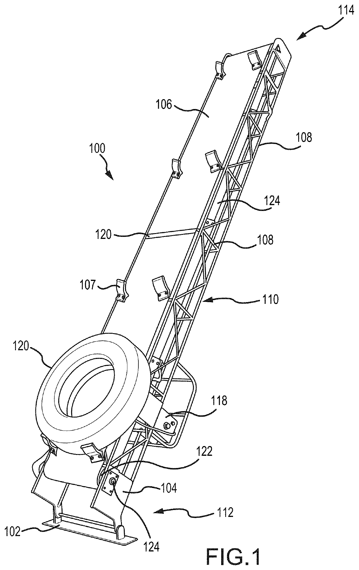
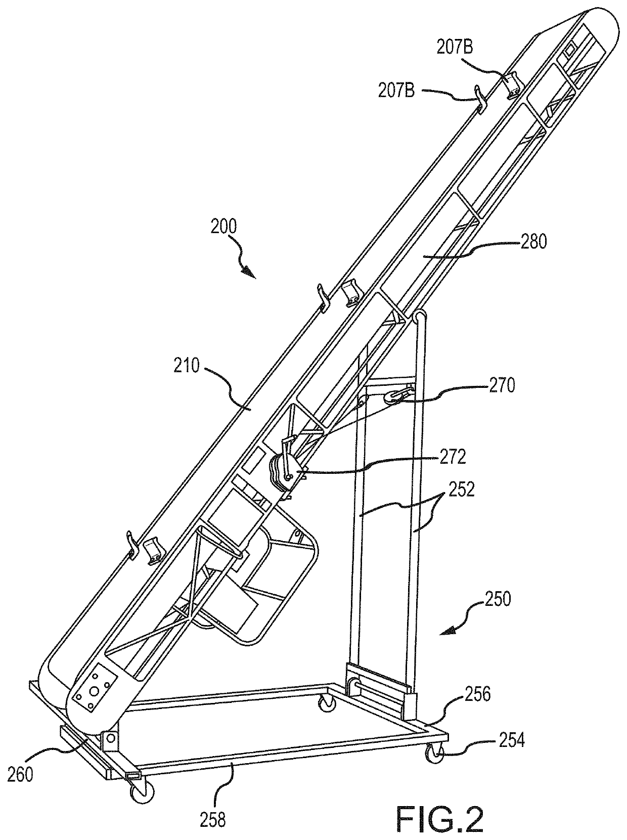
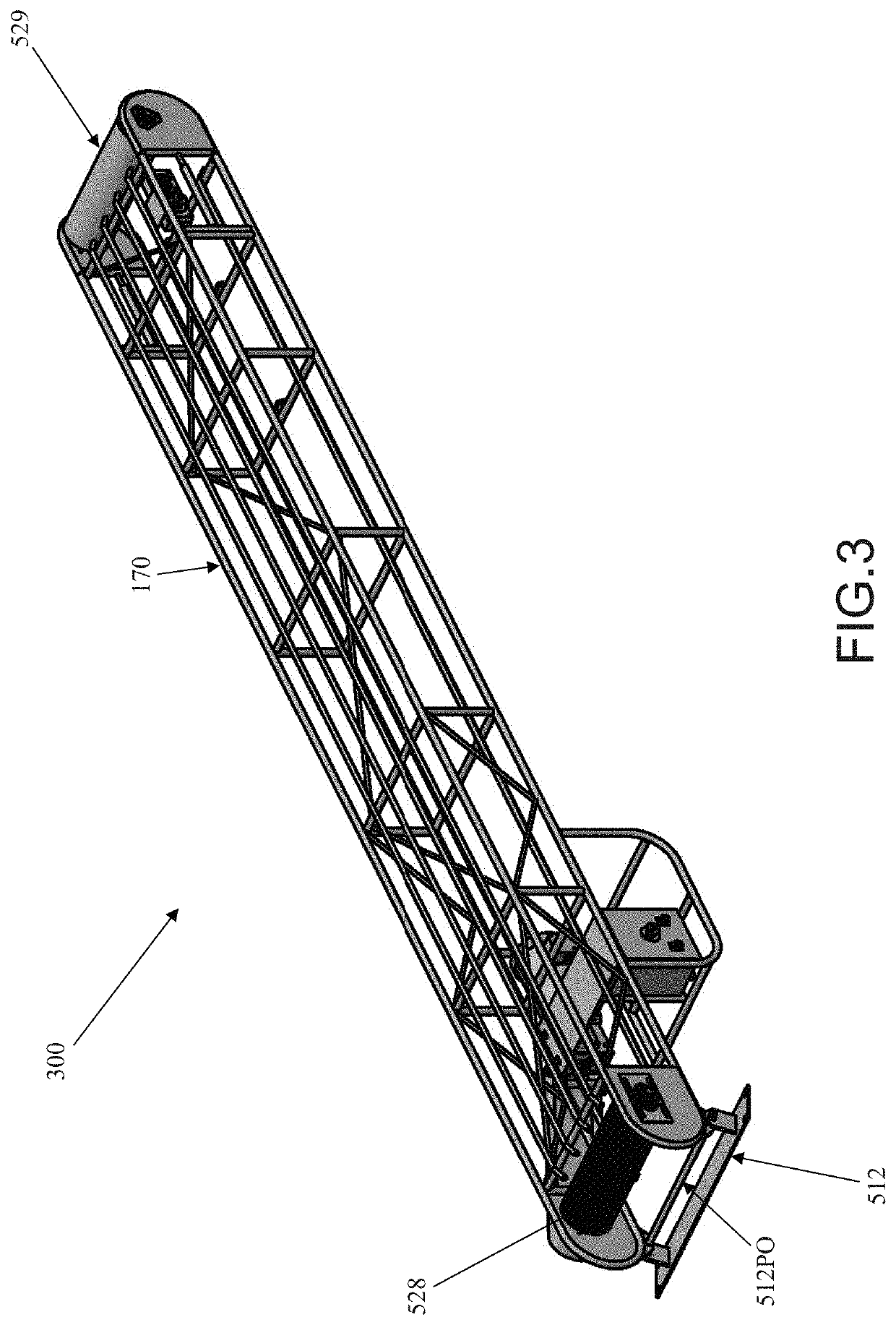
[0238]FIGS. 36A-C show an embodiment of a straight vertical tire conveyor (“VTC”) 3600, where FIG. 36A is a perspective view, FIG. 36B is a front view, and FIG. 36C is a side view of the straight vertical tire conveyor 3600. The VTC 3600 has a bottom end 3612, which is the idle end in some embodiments, and a top end 3614, which is the drive end in some embodiments. The drive end 3614 comprises a motor 3650 positioned within the frame 3608. The VTC 3600 c...


PUM


Abstract

A conveyor for transporting and elevating articles and a method and system for conveying articles up inclines is provided. The conveyor has a conveyor belt and a plurality of support elements extending outward from the article-conveying surface of the conveyor belt advancing upward along the incline. The conveyor may be positioned at an inclined angle relative to the horizontal ground, i.e., between about 5° and 85° or the conveyor can be substantially vertical, i.e., about 90° relative to the horizontal ground. The support elements prevent conveyed articles from sliding down the conveyor belt on the inclined conveyor and carry and hold articles on substantially vertical conveyors. The article-conveying surface of the conveyor belt may provide a low-friction retention surface to articles leaning away from the conveyor belt on the incline.

Description

CROSS-REFERENCE TO RELATED APPLICATIONS[0001]This application is a Continuation-in-Part application of and claims the benefit of priority from U.S. patent application Ser. No. 16 / 119,804, filed Aug. 31, 2018, which is a Continuation Application of and claims the benefit of priority from U.S. patent application Ser. No. 15 / 673,014, filed on Aug. 9, 2017 (now U.S. Pat. No. 10,065,801), which is a Continuation Application of U.S. patent application Ser. No. 15 / 041,668, filed on Feb. 11, 2016 (now U.S. Pat. No. 9,745,133, issued Aug. 29, 2017), which is a Continuation Application of U.S. patent application Ser. No. 14 / 641,126, filed on Mar. 6, 2015 (now U.S. Pat. No. 9,260,247, issued Feb. 16, 2016), which is a Continuation in Part application of U.S. patent application Ser. No. 14 / 154,141, filed on Jan. 13, 2014 (now U.S. Pat. No. 9,061,830, issued Jun. 23, 2015), which claims priority from U.S. Provisional Patent Application No. 61 / 751,722, filed on Jan. 11, 2013, the entire disclosur...

Claims


Application Information

Patent Timeline
Patent Type & Authority Applications(United States)
IPC IPC(8): B65G15/44B65G15/58B65G23/04B07C5/34B07C5/36B65G15/28B65G23/22B65G1/04B65G17/46B65G41/00
CPCB65G23/04B65G2201/0273B65G41/008B65G17/46B65G15/58B65G1/04B65G15/24B65G15/44B07C5/36B07C5/3412B65G15/28B65G23/22B65G41/002B65G19/02
Inventor BACON-MALDONADO, III, JOBDROST, ROBERT D.MILLER, CHRIS K.DROST, KENNETH B.MALDONADO, JR., JOBENSOR, KENTON C.
Owner MULTIELEVATOR
Learn More