Heat exchanger and method of manufacturing heat exchanger

Pending Publication Date: 2020-04-16
DENSO CORP
View PDF2 Cites 1 Cited by
  • Summary
  • Abstract
  • Description
  • Claims
  • Application Information

AI Technical Summary

Benefits of technology

[0010]That is, according to one embodiment of the present disclosure, as each of components of the heat exchanger before brazing, each of components configured to meet the above-described conditions after brazing is used. Subsequently, in the environment of lower oxygen concentration than the atmosphere at either atmospheric pressure or a pressure higher than atmospheric pressure, the heat exchanger is brazed without using flux. With this, three types of braze joining portions including the braze joining portion in which two thin plates join, the braze joining portion in which the thin and thick plates join and the braze joining portion in which two thick plates join can be satisfactory formed. Specifically, the heat exchanger can be satisfactorily brazed at the joining portions.

Problems solved by technology

However, the known technology does not specify conditions of forming the three types of braze joining portions, and simply discusses material of one of the members of the heat exchanger.

Method used


Image

  • Heat exchanger and method of manufacturing heat exchanger
  • Heat exchanger and method of manufacturing heat exchanger
  • Heat exchanger and method of manufacturing heat exchanger

Examples


first embodiment

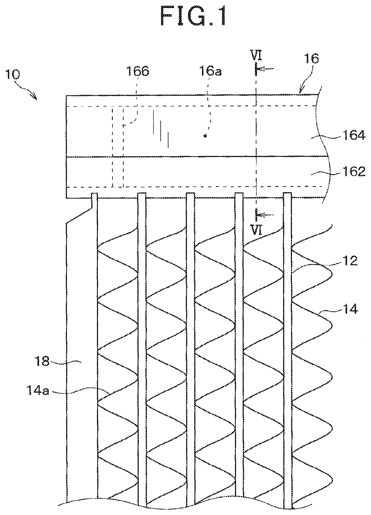
[0050]Referring now to the drawings, wherein like reference numerals designate identical or corresponding parts throughout the several view s thereof, and to FIG. 1, the present disclosure is described. As shown in FIG. 1, a heat exchanger 10 is a fin-tube type heat exchanger in this embodiment. The heat exchanger 10 includes multiple tubes 12 and multiple fins 14, two header tanks 16 and two side plates 18. In FIG. 1, how ever, only one of the two header tanks 16 is illustrated. Also, only one of the two side plates 18 is illustrated. The heat exchanger 10 exchanges heats of a first fluid flown in the multiple tubes 12 and a second fluid flown outside of the multiple tubes 12.

[0051]The tube 12 is a tubular flow channel forming member to form a flow channel for the first fluid. The tube 12 is prepared by molding an aluminum alloy plate into a hollow structure. The tube 12 is also a seam welded pipe prepared by machining a sheet metal. However, the tube 12 can be an extruded perforat...

second embodiment

[0097]Now, the present disclosure is described with reference to FIG. 19A. As shown there, a tube 12 is formed by brazing a plate member subjected to a bending process.

[0098]That is, the tube 12 includes a core material layer 121, a brazing material layer 124 and a cladding layer 125. The brazing material layer 124 is located on one side of the core material layer 121. The brazing material layer 124 is located on an outer surface of the tube 12. The brazing material layer124 may composed of an Al—Si-based alloy. The cladding layer 125 is located on the other side of the core material layer 121 opposite the brazing material layer 124. The cladding layer 125 is thus located inside of the tube 12. The cladding layer 125 is composed of an aluminum alloy (i.e., not a brazing material), such as Al—Zn-based alloy, etc., for example. Further, as shown in FIG. 19A, in each of regions R1 and R2 of the tube 12, the brazing material layer 124 and the cladding layer 125 are joined together.

[0099...

third embodiment

[0101]Now, the present disclosure is described with reference to FIG. 20. As shown in FIG. 20, a fin 15 is disposed inside of the tube 12. The tube 12 is brazed partially sandwiching the fin 15.

[0102]The tube 12 includes a core material layer 121, a brazing material layer 126 and a cladding layer 127. The brazing material layer 126 is located on one side of the core material layer 121. The brazing material layer 126 is located on an inner side of the tube 12. The brazing material layer 126 is composed of an Al—Si-based alloy. The cladding layer 127 is located on a side of the core material layer 121 opposite the brazing material layer 126. The cladding layer 127 is composed of an aluminum alloy excluding brazing material, for example, an Al—Zn-based alloy. The fin 15 may consist of the core material layer 151 composed of an Al—Mn-based alloy.

[0103]As shown in FIG. 20, in a region R3 of the tube 12, the brazing material layer 126 and the cladding layer 127 are joined together. As in ...


PUM

PropertyMeasurementUnit
thicknessaaaaaaaaaa
thicknessaaaaaaaaaa
thicknessaaaaaaaaaa

Abstract

Mg and Bi are contained in each of a first fillet in a first braze joining portion in which a tube and a fin join, a second fillet in a second braze joining portion in which the tube and a header plate join, and a third fillet in a third braze joining portion in which the header plate and a tank body join. A concentration of Mg of each of the first to third fillets is from 0.2% or more to 2.0% or less by mass. When the tube includes a brazing material layer, a concentration of Mg of the tube at its plate thickness center is from 0.1% or more to 1.0% or less by mass. When the fin includes a brazing material layer, a concentration of Mg of the fin at its plate thickness center is from 0.2% or more to 1.0% or less by mass.

Description

CROSS-REFERENCE TO RELATED APPLICATION[0001]This patent application is based on and claims priority to Japanese Patent Application 2018-192060, filed on October 10,2018 in the Japan Patent Office, the entire disclosure of which is hereby incorporated by reference herein.BACKGROUNDTechnical Field[0002]Embodiments of this disclosure relate to a heat exchanger and a method of manufacturing the heat exchanger.Related Art[0003]A technology of brazing an aluminum member in an inert gas atmosphere without using flux is known. With the known technology, the aluminum member is brazed in a lower oxygen concentration environment than the atmosphere at atmospheric pressure without using flux or vacuum. To effectively join a hollow structure and a cylindrical member together, a known technology specifies material of each of components of the hollow structure.[0004]However, since an aluminum alloy heat exchanger is configured by multiple components respectively having different plate thicknesses ...

Claims


Application Information

Patent Timeline
Patent Type & Authority Applications(United States)
IPC IPC(8): F28F21/08B23K1/00B23K35/28B21D53/02F28D1/053
CPCB23K1/0012F28D1/053F28F21/084B21D53/02B23K2101/14B23K35/286B23K2103/10F28D7/00F28D9/00F28F9/268B23K1/0008F28F2275/04F28D1/0333F28D1/05366F28D9/005F28F3/025F28F1/126
Inventor SHINODA, TAKAHIROYAMADA, SHOGOHONMA, NOBUHIROSUGIMOTO, NAOKITOYAMA, TAKETOSHI
Owner DENSO CORP
Why Eureka
Try Eureka