
Systems and methods for compensating coherent optics delay asymmetry in a packet optical network

a technology of coherent optics and optical networks, applied in the field of optical networking, can solve the problems of different delays in the forward and reverse directions, difficult timing accuracy, and difficulty in transferring time over optical networks, and achieve the effect of reducing delay asymmetry

Active Publication Date: 2020-01-23
CIENA
View PDF5 Cites 17 Cited by
  • Summary
  • Abstract
  • Description
  • Claims
  • Application Information

AI Technical Summary

Benefits of technology

The patent describes a way to reduce delays in optical equipment by using software. This approach can be used in devices like modems and DSP devices, which don't have built-in time transfer functions. This can improve the speed and accuracy of data transfer in optical networks.

Problems solved by technology

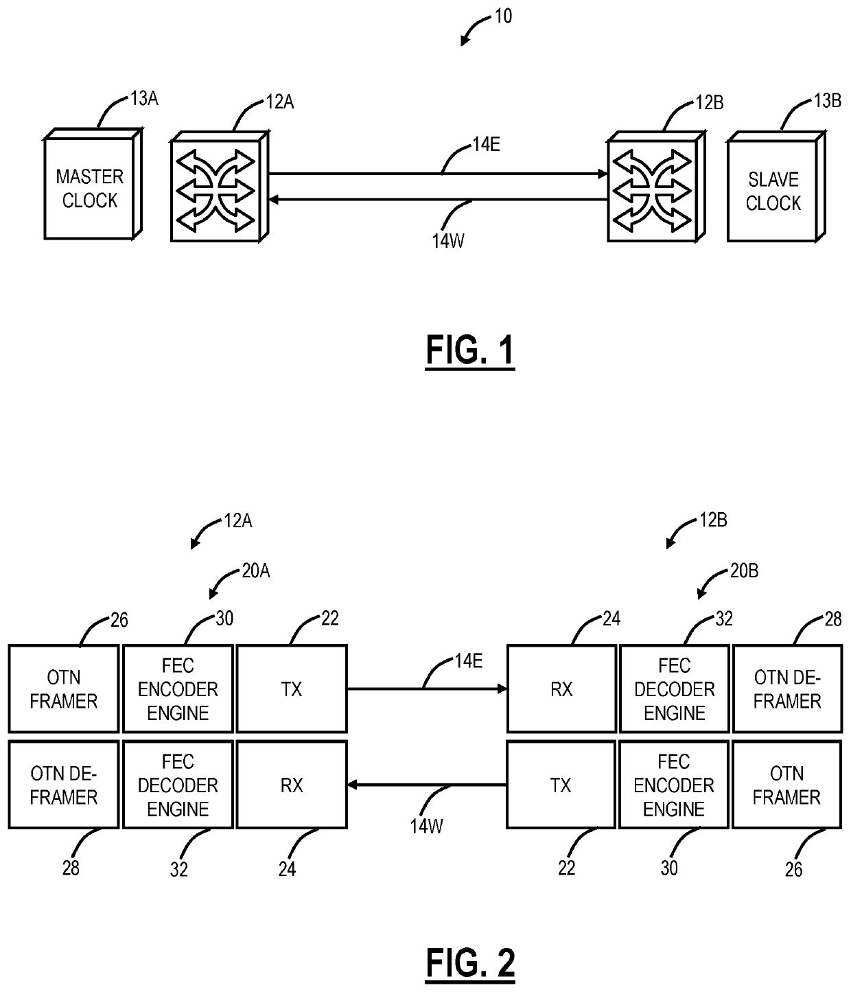
Timing accuracy is more difficult with OTN and coherent optics with OTN having asynchronous mappings and coherent optics introducing variable delays which may be different in a transmit and receive direction.
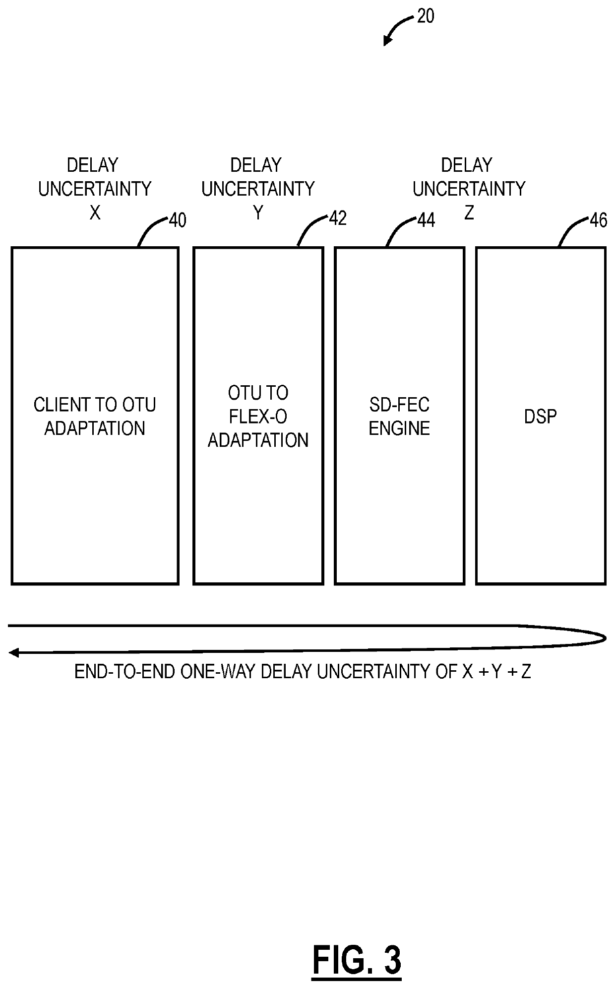
The transfer of time over optical networks can be challenging because of delays introduced by elastic First-In-First-Out (FIFO) or queues required in transport mapping schemes such as OTN and enhanced high coding gain Soft-Decision Forward Error Correction (SD-FEC) schemes.
Variability in these delays (at start-up, or after fault recovery) can result in different delays in the forward and reverse direction, referred to as delay asymmetry.
When transferring time across a network, the delay asymmetry results in a time error.
It does not address performance aspects such as the time accuracy that can be achieved over a network.
Based on current 100 Gb / s system designs, measurements have shown that the optical transport equipment can contribute hundreds of nanoseconds of time uncertainty over a single network hop.
Measurements of some off-the-shelf components have shown much worse performance.
Newly developed standards have not yet addressed time uncertainty and jitter that can be introduced by SD-FEC type of schemes added on the line side in optical modem / Digital Signal Processing (DSP) devices.

Method used


Image

  • Systems and methods for compensating coherent optics delay asymmetry in a packet optical network
  • Systems and methods for compensating coherent optics delay asymmetry in a packet optical network
  • Systems and methods for compensating coherent optics delay asymmetry in a packet optical network

Examples


example controller

[0059]FIG. 8 is a block diagram of a controller 300 to provide control plane processing and / or operations, administration, maintenance, and provisioning (OAM&P) for the node 12. The controller 300 can be part of the common equipment, such as the common equipment 210 in the node 12, or a stand-alone device communicatively coupled to the node 12 via the DCN 260. The controller 300 can include a processor 310 which is a hardware device for executing software instructions such as operating the control plane. The processor 310 can be any custom made or commercially available processor, a central processing unit (CPU), an auxiliary processor among several processors associated with the controller 300, a semiconductor-based microprocessor (in the form of a microchip or chip set), or generally any device for executing software instructions. When the controller 300 is in operation, the processor 310 is configured to execute software stored within the memory, to communicate data to and from t...


PUM


Abstract

Systems and methods of compensating for the delay asymmetry of coherent optical modems in a packet optical network include measuring fill levels of one or more queues each including an elastic First-In-First-Out (FIFO) circuit used in a transport mapping scheme, wherein the transport mapping scheme is one or more of client mapping to Optical Transport Unit (OTU) and OTU mapping to Flexible OTN (FlexO); and performing adjustments in a clock based in part on the measured fill levels, wherein the adjustments are configured to reduce a Time Error (TE) in the packet network based on delay asymmetry between two nodes.

Description

FIELD OF THE DISCLOSURE[0001]The present disclosure generally relates to optical networking. More particularly, the present disclosure relates to systems and methods for compensating coherent optics delay asymmetry in a packet optical network.BACKGROUND OF THE DISCLOSURE[0002]Timing accuracy is important in various network applications, such as wireless base station synchronization, etc. Packet networks operate over optical networks which are evolving to use Optical Transport Network (OTN), Flexible Optical (FlexO), and coherent optics. Frequency synchronization across a network was been previously performed with Synchronous Optical Network (SONET), Synchronous Digital Hierarchy (SDH), and synchronous Ethernet. Timing distribution has been evolved to use IEEE 1588 to enable phase and time synchronization across a network. Timing accuracy is more difficult with OTN and coherent optics with OTN having asynchronous mappings and coherent optics introducing variable delays which may be d...

Claims


Application Information

Patent Timeline
IPC IPC(8): H04B10/079H04Q11/00H04L7/00
CPCH04Q11/0066H04B10/0795H04L7/0075H04B10/0773H04J3/0623H04J3/0647H04J3/065H04J3/0667H04J2203/0085
Inventor ABDULLAH, BASHARPERRAS, DANIELGAREAU, SEBASTIENLIU, XIAOJIN
Owner CIENA
Learn More