
Electrode sheet manufacturing method and electrode sheet manufacturing apparatus

Active Publication Date: 2020-01-09
TORAY ENG CO LTD +1
View PDF0 Cites 1 Cited by
  • Summary
  • Abstract
  • Description
  • Claims
  • Application Information

AI Technical Summary

Benefits of technology

The present invention provides a method and apparatus for manufacturing an electrode sheet with high quality. By pressing the cutting blade into the sheet body from the support layer side, the cutting active layer can be easily performed without generating burrs and contamination. The separation of the support layer from the cutting blade creates a tensile stress on the active layer, which prevents deformation and chipping. Overall, this method allows for easy and efficient production of electrode sheets.

Problems solved by technology

Therefore, an outer edge of the active layer that constitutes the electrode sheet may become deformed or chipped off.
Further, in the event that burrs are generated in the support layer at the time of cutting the sheet body, there is a concern that such burrs may protrude outwardly of the electrode sheet.
Furthermore, there is a possibility that the surface of the active layer may become contaminated in a conveying step that takes place after completion of the punching process.

Method used


Image

  • Electrode sheet manufacturing method and electrode sheet manufacturing apparatus
  • Electrode sheet manufacturing method and electrode sheet manufacturing apparatus
  • Electrode sheet manufacturing method and electrode sheet manufacturing apparatus

Examples


first embodiment

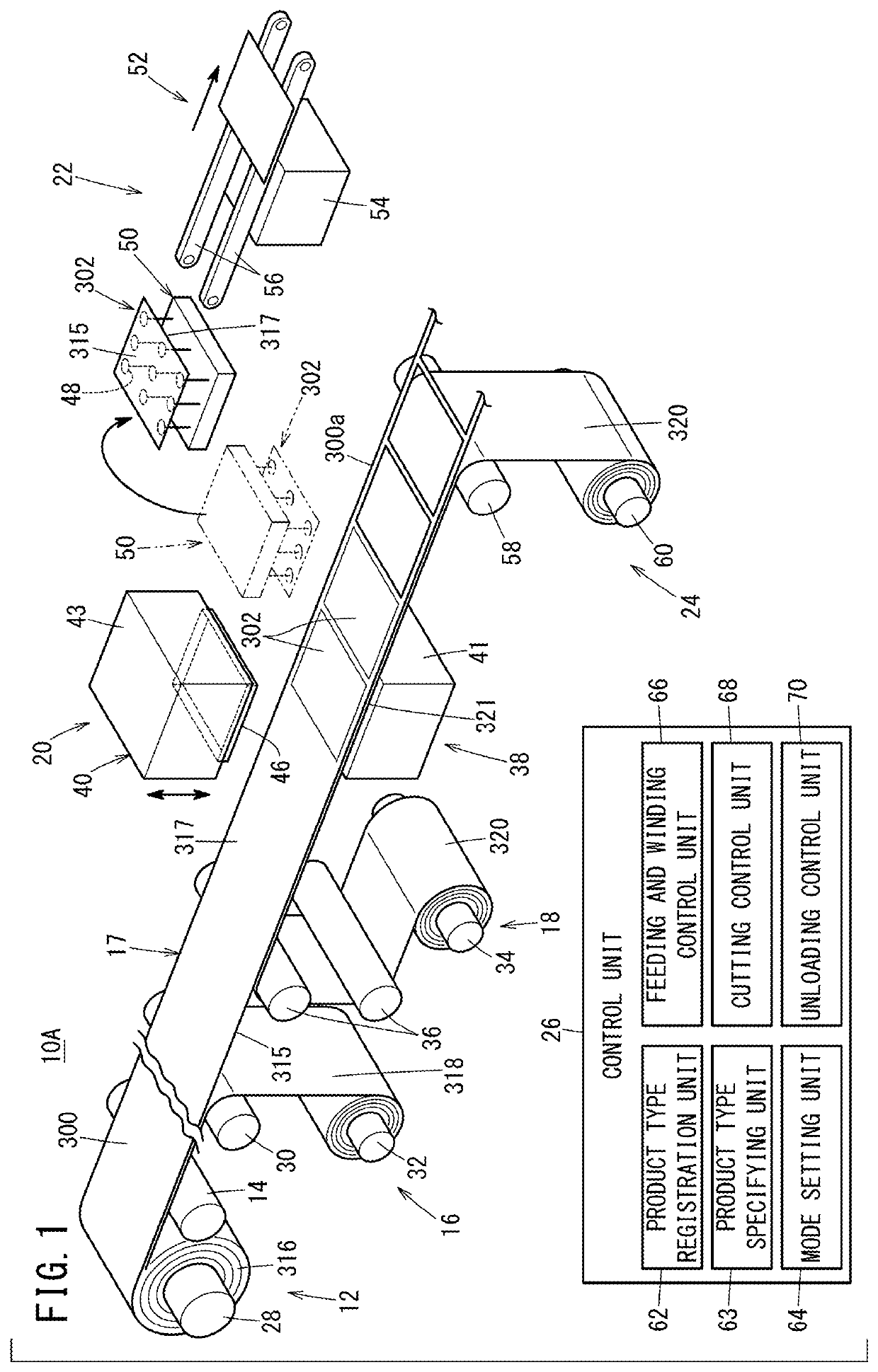
[0021]As shown in FIG. 1, a manufacturing apparatus 10A for manufacturing an electrode sheet 302 according to the present embodiment forms the electrode sheet 302 for use in a fuel cell 304 (see FIG. 2) by cutting a sheet body 300. However, the manufacturing apparatus 10A is not limited to an example in which the electrode sheet 302 is manufactured for use with the fuel cell 304, and it goes without saying that electrode sheets other than for use with such a fuel cell 304 may be formed.

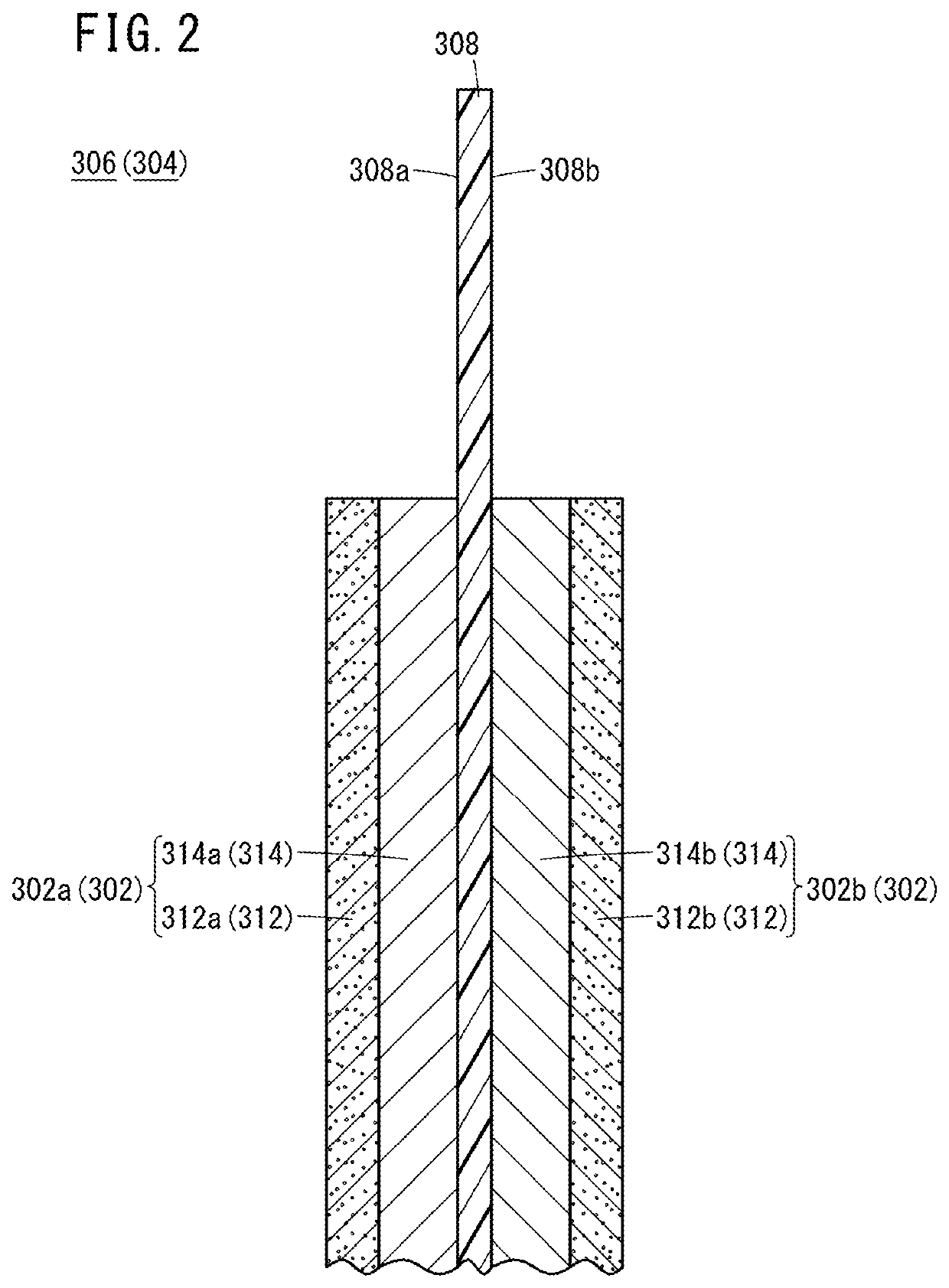
[0022]First, the electrode sheet 302 for use with the fuel cell 304 will be described. In FIG. 2, for example, a solid polymer electrolyte fuel cell 304 includes a membrane electrode assembly 306. The membrane electrode assembly 306 includes an electrolyte membrane 308, an anode side electrode sheet 302a disposed on one surface 308a of the electrolyte membrane 308, and a cathode side electrode sheet 302b disposed on another surface 308b of the electrolyte membrane 308.

[0023]The anode side electrode sh...

second embodiment

[0112]Next, a manufacturing apparatus 10B for manufacturing the electrode sheet 302 and a method of manufacturing the electrode sheet 302 according to a second embodiment of the present invention will be described. In the manufacturing apparatus 10B for manufacturing the electrode sheet 302 according to the second embodiment, the same reference characters are used to designate the same constituent elements as those described in connection with the above-described first embodiment, and detailed description of such features is omitted.

[0113]Further, in the method of manufacturing the electrode sheet 302 according to the second embodiment, descriptions concerning steps which are the same as steps that have already been described in connection with the aforementioned first embodiment will be omitted. Furthermore, in the present embodiment, the same operations and effects are realized in relation to the same constituent elements and steps as those constituent elements and steps described...

third embodiment

[0117]Next, a manufacturing apparatus 10C for manufacturing the electrode sheet 302 and a method of manufacturing the electrode sheet 302 according to a third embodiment of the present invention will be described.

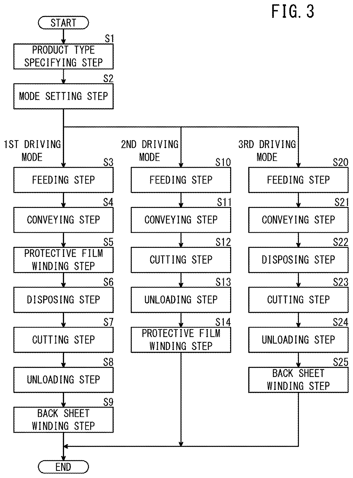
[0118]As shown in FIG. 9B, in the manufacturing apparatus 10C, the upstream side winding unit 16 and the back sheet feeding unit 18 which were described above are omitted. Stated otherwise, in the method of manufacturing in which the manufacturing apparatus 10C is used, only the above-described second driving mode is carried out. In this case, since there is no need to provide the upstream side winding unit 16 and the back sheet feeding unit 18, the configuration of the manufacturing apparatus 10C can be simplified, as compared with the manufacturing apparatus 10A according to the first embodiment.

[0119]In the manufacturing apparatus 10C, the downstream side winding unit 24 may additionally be omitted. In this case, the configuration of the manufacturing apparatus 10C can b...


PUM


Abstract

A method of manufacturing an electrode sheet by using an electrode sheet manufacturing apparatus for manufacturing the electrode sheet includes a feeding step of feeding out a sheet body from a roll on which the sheet body is wound, the sheet body including an active layer containing a catalyst laminated on a support layer, and a cutting step of forming the electrode sheet by punching the sheet body by pressing a cutting blade from a side of the support layer against the sheet body that was fed out in the feeding step.

Description

CROSS-REFERENCE TO RELATED APPLICATION[0001]This application is based upon and claims the benefit of priority from Japanese Patent Application No. 2018-127362 filed on Jul. 4, 2018, the contents of which are incorporated herein by reference.BACKGROUND OF THE INVENTIONField of the Invention[0002]The present invention relates to a method of manufacturing an electrode sheet and to an apparatus for manufacturing such an electrode sheet which is formed by cutting a sheet body.Description of the Related Art[0003]A fuel cell includes a membrane electrode assembly (MEA) in which electrode sheets are disposed on both sides of an electrolyte membrane. The electrode sheets are constituted by laminating a catalyst layer on a gas diffusion layer. In manufacturing such a membrane electrode assembly, a method is known in which a gas diffusion layer is formed as a standalone item by cutting the gas diffusion layer, and then the gas diffusion layer is laminated onto a catalyst layer which is dispose...

Claims


Application Information

Patent Timeline
IPC IPC(8): H01M4/04H01M4/88H01M8/0271H01M8/04082H01M8/04746
CPCH01M8/04201H01M8/04746H01M4/0409H01M4/8896H01M8/0271H01M4/8875H01M4/8878Y02E60/10Y02E60/50Y02P70/50
Inventor KATAYAMA, KEISUKEHAYAKAWA, TAKUTOWADA, YUSUKEKURIMOTO, MASAMI
Owner TORAY ENG CO LTD
Learn More