
Fuel Cell Module

Active Publication Date: 2016-05-19
TOYOTA JIDOSHA KK
View PDF1 Cites 1 Cited by
  • Summary
  • Abstract
  • Description
  • Claims
  • Application Information

AI Technical Summary

Benefits of technology

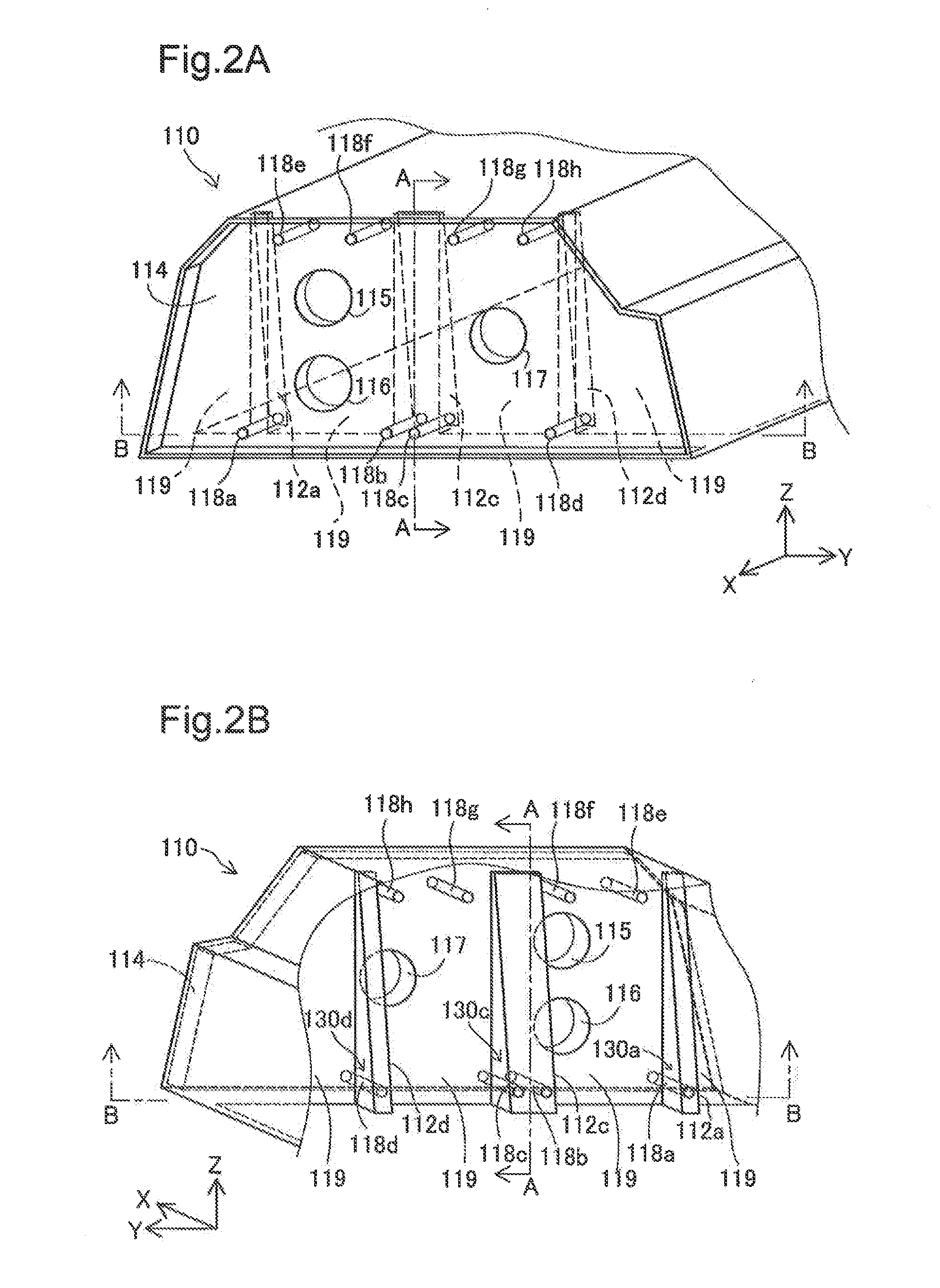
The patent text describes a fuel cell module which includes a fuel cell and a case housing it. The fuel cell module has a cell stack with multiple stacked unit cells and a pressure plate arranged at the outermost position of the cell stack. The case has a cover section covering the pressure plate, which has a thick part formed inward of the case. The thick part provides additional rigidity to the case in the area near the through hole where the pin is placed. This prevents deformation of the case due to the force from the cell stack. The fuel cell module has a pin housing portion with a through hole, which allows for adjustment of the pressing force with a large margin of adjustment. This reduces the number of pins required for adjustment and suppresses the increase in operational cost of the fuel cell module. The pin housing portion has a continuous thin and thick part, which allows for a larger empty region between the cover section and the pressure plate, reducing the size of the entire fuel cell module. The pin housing portion also has a rib that increases the rigidity of the cover section. This structure makes the case easier to manufacture and prevents damage to the pressure plate due to collisions.

Problems solved by technology

This causes a problem of deformation of the case near the screw hole.
Additionally, a distance between the pressure plate and the case may become nonuniform due to nonuniformity of the thickness of the unit cell occurring during manufacture and loosening of the screw during operation, for example.
However, depending on the length of the screw hole (screw thread) provided to the case, the length of the load adjusting screw might become insufficient or the rear end of the load adjusting screw might protrude from the case.
To avoid such risks, several types of load adjusting screws of different lengths should be prepared as load adjusting screws for maintenance of a fuel cell module, causing increase in operational cost of the fuel cell module.
This can make it unlikely that the length of the pin will become insufficient or the rear end of the pin will protrude from the case during adjustment of pressing force.
Additionally, on the occurrence of collision of a mobile object such as a fuel cell vehicle on which the fuel cell module including the case is installed with an object such as a different vehicle, for example, this structure can make damage on the pressure plate unlikely that is to be caused by an edge of this step.

Method used


Image

  • Fuel Cell Module
  • Fuel Cell Module
  • Fuel Cell Module

Examples


embodiment

A. Embodiment

A-1. Structure of Entire Module

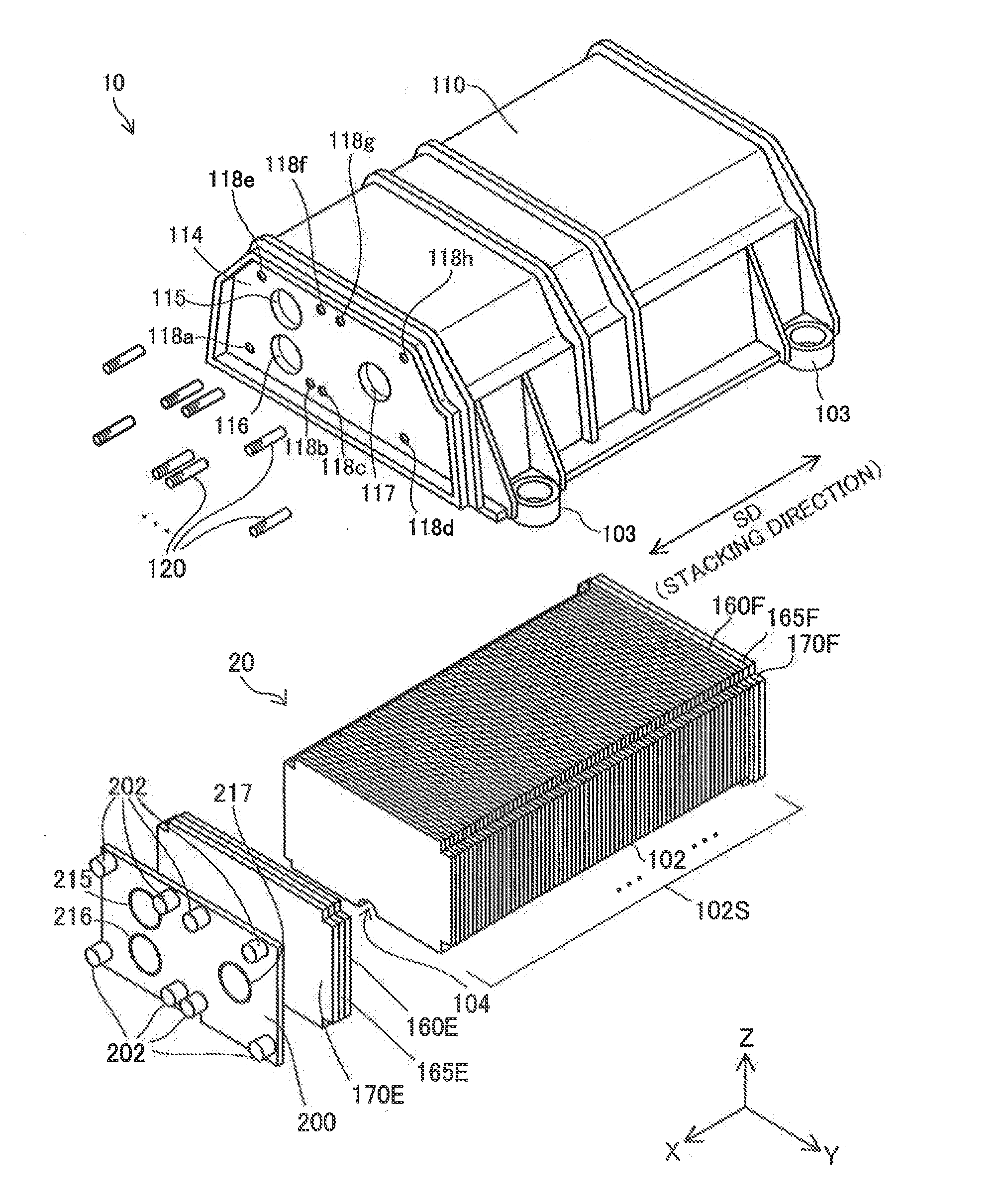
[0024]FIG. 1 is an exploded perspective view showing the outline of the structure of a fuel cell module as an embodiment of this invention. FIG. 1 is an exploded view of a part of a fuel cell module 10 of this embodiment. In FIG. 1, an X-Y plane corresponds to a horizontal plane. Further, an X axis, a Y axis, and a Z axis are determined in a manner such that the Z axis extends parallel to a vertical direction. A +Z direction corresponds to an upward vertical direction. The fuel cell module 10 of this embodiment is installed on and used in a fuel cell vehicle as a driving power source. More specifically, when the fuel cell module 10 is to be used, the fuel cell module 10 is fixed with bolts to the underbody of a fuel cell vehicle through case legs 103 of the case 110. Instead of a fuel cell vehicle, the fuel cell module 10 may be installed on and used in any other mobile object requiring a power source. Still alternatively, the fuel cell mo...

first modification

B1. First Modification

[0047]In the aforementioned embodiment, the thickness of the pin housing portion 112c (the length in the X-axis direction) is minimum at the end part thereof in the +Z direction and becomes larger gradually toward the −Z direction, to which this invention is not limited.

[0048]FIG. 6 is a sectional view showing the structure of a cover section of a first aspect of a modification. A fuel cell module of the first aspect of the modification differs from the fuel cell module 10 of the aforementioned embodiment in that it includes a case 110a instead of the case 110. The fuel cell module of the first aspect of the modification is the same in every other respect as the fuel cell module 10. Corresponding components are identified by the same signs and will not be described in detail. In the fuel cell module of the first aspect of the modification, the case 110a differs from the case 110 of the aforementioned embodiment in that it includes a cover section 114a instead o...

third modification

B3. Third Modification

[0058]In the aforementioned embodiment, each of the pin housing portions 112a, 112c, and 112d extends in the Z-axis direction. In the third aspect of the modification, each of the pin housing portions 108a and 108b extends in the Y-axis direction. In a structure where each pin housing portion has an outer shape like a rib, however, a direction where each pin housing portion extends is not limited to the Z-axis direction or the Y-axis direction but each pin housing portion may extend in any direction that crosses the stacking direction SD.


PUM


Abstract

A fuel cell module includes a fuel cell and a case housing the fuel cell. The fuel cell includes a cell stack and a pressure plate arranged at an outermost position of a stacking direction relative to the cell stack. The case includes a cover section that faces the pressure plate and covers the pressure plate while the fuel cell is housed in the case. The cover section includes a pin housing portion having a through hole and a pin placed in the through hole with which the pressure plate is pressed. The pin housing portion has a thick part thicker than a thin part that is at least a part of the cover section continuous with the pin housing portion. The thick part is formed in an inward direction of the case.

Description

CROSS-REFERENCE TO RELATED APPLICATIONS[0001]The present application claims the priority based on the Japanese Patent Application No. 2014-230528 filed on Nov. 13, 2014, the entirety of disclosure of which is hereby incorporated by reference into this application.BACKGROUND[0002]1. Field[0003]This invention relates to a fuel cell module including a fuel cell and a case housing the fuel cell.[0004]2. Related Art[0005]Some fuel cell including a cell stack as a stack of multiple unit cells is housed in a box-like case and used therein. Application of a load to the cell stack in a stacking direction has been required in order to maintain each of the unit cells in a stacked state inside the case. This may be achieved by a fuel cell suggested for example in JP2013-12325A. In this fuel cell, a pressure plate having an end surface substantially the same in size as an end surface of the cell stack is arranged outside the cell stack in the stacking direction so as to face an inner surface of ...

Claims


Application Information

Patent Timeline
IPC IPC(8): H01M8/24
CPCH01M8/248H01M8/2475H01M8/249Y02E60/50
Inventor TAKEYAMA, MAKOTO
Owner TOYOTA JIDOSHA KK
Learn More