Detector for optically detecting at least one object

Pending Publication Date: 2020-01-09
TRINAMIX GMBH
View PDF3 Cites 29 Cited by
  • Summary
  • Abstract
  • Description
  • Claims
  • Application Information

AI Technical Summary

Benefits of technology

This patent is about a device that measures the position of an object by measuring the amount of light that is reflected or transmitted from it. The device is designed to have a wide range of measurements, depending on the brightness or power of the light beam. This is possible because the device uses a special optical element that weakens the light at certain angles, which helps to cut off unwanted light. Overall, the device provides a more accurate and reliable method for measuring the position of objects.

Problems solved by technology

However, edge detection may be only possible at relatively short distances from the object to the detector.
However, such detectors may require mechanical movement of detector components to ensure that the object is in a focus of an optical system of the detector.
Because the laser energy is spread over a line, it is difficult to achieve accurate range, especially in the presence of ambient light, or with darker objects.
Such devices cannot be miniaturized, and their cost and mechanical fragility will remain high.
Although modulation techniques can be used to offset some of the effects of ambient light, PSDs do not perform well unless the laser spot has a very strong reflection, limiting their use to ranges of a meter or less.
Despite the advantages implied by the above-mentioned devices and detectors, several technical challenges remain.
Still, large area sensors in many cases are inherently limited in the use of the FiP measurement principle, specifically in case more than one light spot is to be investigated simultaneously.
A further challenge using FiP detectors is detector area or active area.
This area, however, may cause noise problems, specifically when the tetralateral conductivity concept is employed to build a PSD.
This often results in poor signal-to-noise-ratios and slow detector response times due to the large capacitance in conjunction with the series resistance of the detector.
A further challenge using FiP detectors is cost of manufacturing.
Thus, in many cases, typical FiP sensors are expensive, as compared to e.g. conventional Si-based photodiodes.
Further, the evaluation of the measurement results of measurements using FiP-sensors remains an issue, specifically in case the total power of a light beam is unknown.
Further, many FiP-detectors show a luminance dependency which renders the evaluation of the measurement result more difficult, and, additionally, FiP-measurements in many cases are dependent on a target spot size.
Referring to concepts comparing sensor signals generated by at least two different sources such as at least two different optical sensors, one technical challenge remains a reduction of cost of the overall system and, specifically, of the optical sensors.
Thus, in many concepts, special optical sensors have to be used, having a dedicated design and placement, which typically requires setting up an expensive optoelectronic semiconductor manufacturing process and a complex assembly scheme.
A further technical challenge may be measuring the distance of at least one object through an optical fiber.
Using known methods such as time of flight or triangulation methods accurate determination of the distance through the optical fiber is very demanding.
Further, in particular for time of flight measurements light travelling time through the fiber may not be accurate enough.

Method used


Image

  • Detector for optically detecting at least one object
  • Detector for optically detecting at least one object
  • Detector for optically detecting at least one object

Examples


Embodiment Construction

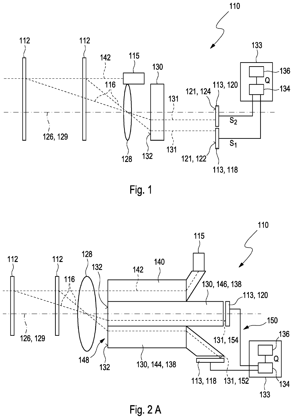
[0461]In FIG. 1, a schematic view of an exemplary embodiment of a detector 110 for determining a position of at least one object 112 is depicted. In FIG. 1, the object 112 is depicted for two different object distances. The detector 110 comprises at least two optical sensors 113, for example a first optical sensor 118 and a second optical sensor 120, each having at least one light-sensitive area 121. The object 112 may comprise at least one beacon device 114, from which a light beam 116, also denoted as incident light beam, propagates towards the detector 110. Additionally or alternatively, the detector may comprise at least one illumination source 115 for illuminating the object 112. As an example, the illumination source 115 may be configured for generating an illuminating light beam for illuminating the object 112. Specifically, the illumination source 115 may comprise at least one laser and / or laser source. Various types of lasers may be employed, such as semiconductor lasers. A...


PUM


Abstract

A detector (110) for determining a position of at least one object is proposed. The detector (110) comprises: —at least one angle dependent optical element (130) adapted to generate at least one light beam (131) having at least one beam profile depending on an angle of incidence of an incident light beam (116) propagating from the object (112) towards the detector (110) and illuminating the angle dependent optical element (130), wherein the angle dependent optical element (130) comprises at least one optical element selected from the group consisting of: at least one optical fiber, in particular at least one multifurcated optical fiber, in particular at least one bifurcated optical fiber; at least one diffractive optical element; at least one angle dependent reflective element, at least one diffractive grating element, in particular a blaze grating element; at least one aperture stop; at least one prism; at least one lens; at least one lens array, in particular at least one microlens array; at least one optical filter; at least one polarization filter; at least one bandpass filter; at least one liquid crystal filter, in particular a liquid crystal tunable filter; at least one short-pass filter; at least one long-pass filter; at least one notch filter; at least one interference filter; at least one transmission grating; at least one nonlinear optical element, in particular one birfringent optical element; —at least two optical sensors (113), wherein each optical sensor (113) has at least one light sensitive area (121), wherein each optical sensor (113) is designed to generate at least one sensor signal in response to an illumination of its respective light-sensitive area by the light beam (131) generated by the angle dependent optical element (130); at least one evaluation device (133) being configured for determining at least one longitudinal coordinate z of the object (112) by evaluating a combined signal Q from the sensor signals.

Description

FIELD OF THE INVENTION[0001]The invention relates to a detector, a detector system and a method for determining a position of at least one object. The invention further relates to a human-machine interface for exchanging at least one item of information between a user and a machine, an entertainment device, a tracking system, a camera, a scanning system and various uses of the detector device. The devices, systems, methods and uses according to the present invention specifically may be employed for example in various areas of daily life, gaming, traffic technology, production technology, security technology, photography such as digital photography or video photography for arts, documentation or technical purposes, medical technology or in the sciences. Further, the invention specifically may be used for scanning one or more objects and / or for scanning a scenery, such as for generating a depth profile of an object or of a scenery, e.g. in the field of architecture, metrology, archaeo...

Claims


Application Information

Patent Timeline
IPC IPC(8): G01S17/46G01S3/783G01S7/481G01S7/48
CPCG01S7/4814G01S7/4816G01S7/4808G01S7/4817G01S7/4818G01S17/46G01S3/783G01S17/42G01S17/89G01S17/48
Inventor SEND, ROBERTOEGUEN, CELAL MOHANHAHNE, CHRISTOPHEREBERSPACH, MICHAELBRUDER, INGMARSCHERWATH, BERND
Owner TRINAMIX GMBH
Why Eureka
Try Eureka