
Stroke determination device for 4-stroke engine

a four-stroke engine and determination device technology, which is applied in the direction of electric control, machines/engines, mechanical equipment, etc., can solve the problems of increased cost of engine control devices, increased complexity of engine structure, and inability to determine stroke, so as to reduce the performance of ignition devices, reduce the cost, and facilitate the detection of stroke determination parameters

Active Publication Date: 2020-01-09
MAHLE INT GMBH
View PDF0 Cites 0 Cited by
  • Summary
  • Abstract
  • Description
  • Claims
  • Application Information

AI Technical Summary

Benefits of technology

The present invention relates to an ignition coil with a secondary coil for detecting the stroke (the time it takes for a piston to move in a cylinder) of an engine. The secondary coil is made up of two parts, and the stroke determination parameter is detected from the waveform of the voltage at the boundary between these parts. This allows for the detection of the stroke using a low-cost element, without the need for extra components or a reduction in the performance of the ignition device. Additionally, the stroke determination parameter is accurately detected from the waveform of voltage or current, without being affected by spike-form waves.

Problems solved by technology

However, in a four-stroke engine, a single combustion cycle is performed during two rotations of the crankshaft, and therefore, the stroke cannot be determined merely by detecting the crank angle position.
However, there is a problem in that the structure of the engine increases in complexity and the cost of the engine control device is increased when sensors that generate pulse signals are mounted on both the crankshaft and the camshaft.
However, when the combustion in the expansion stroke is insufficient and the ignition operation is performed near the crank angle position corresponding to top dead center of the exhaust stroke, the fuel remaining in the cylinder combusts and afterfire occurs, which may damage the engine.
Additionally, when the ignition operation is performed in both the expansion stroke and the compression stroke, there is a problem in that the frequency of sparking in the spark plug is increased, and the service life of the spark plug is therefore reduced.

Method used


Image

  • Stroke determination device for 4-stroke engine
  • Stroke determination device for 4-stroke engine
  • Stroke determination device for 4-stroke engine

Examples


Embodiment Construction

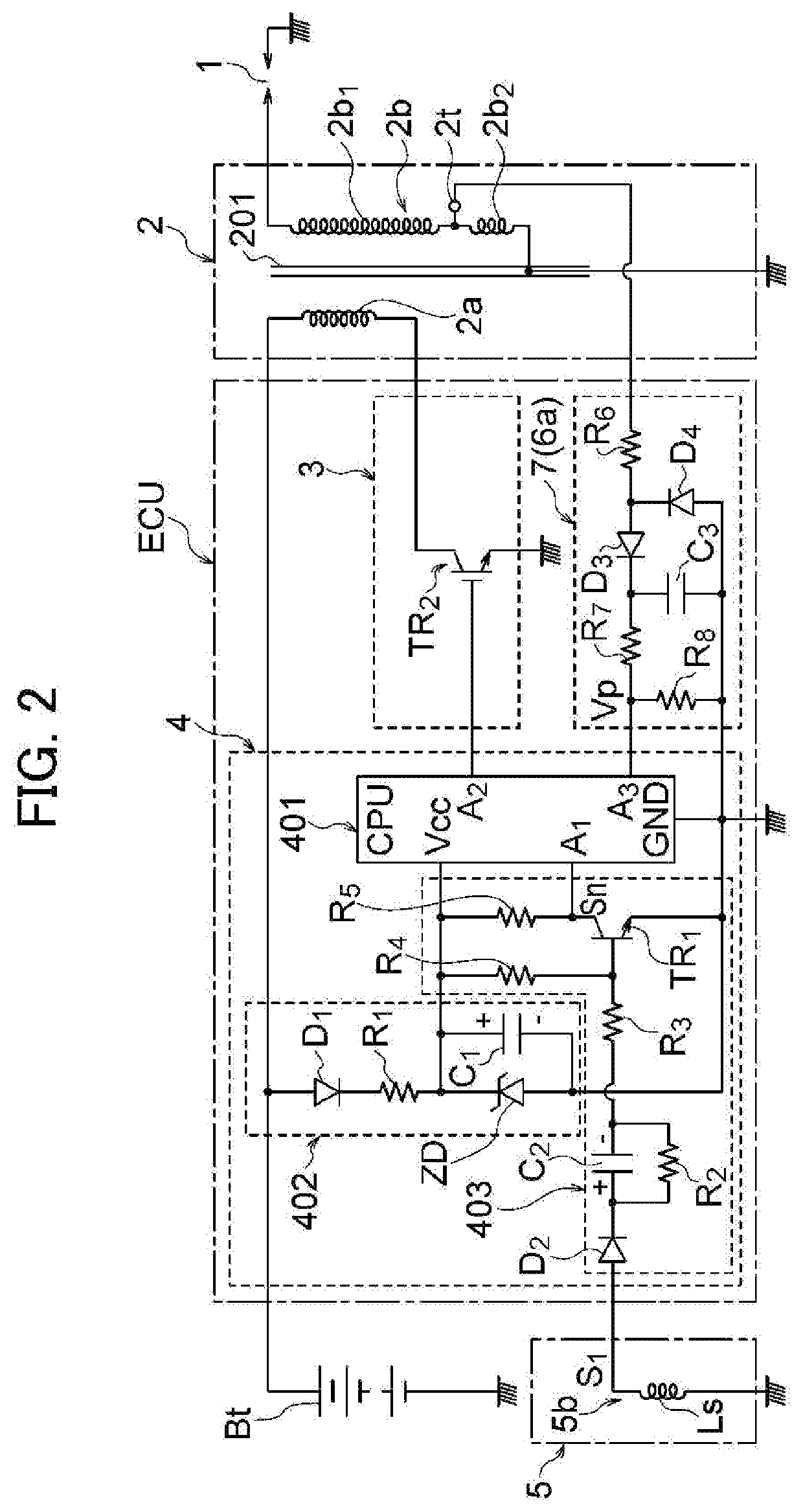
[0065]The present invention pertains to a stroke determination device for establishing whether a stroke carried out in the cylinders is an exhaust stroke or a compression stroke when an ignition operation is carried out in the cylinders of a four-stroke engine comprising an engine body having at least one cylinder, and an ignition device having an ignition coil provided for each cylinder and that induces a high voltage in a secondary coil of an ignition coil by controlling a primary current of the ignition coil, ignition being performed by application of a high voltage induced in the secondary coil of the ignition coil of the ignition device to a spark plug. The stroke determination device according to the present invention extracts a stroke determination parameter from the waveform of voltage or the waveform of current detected from the secondary side of the ignition coil of the ignition device, and determines the stroke using the extracted parameter. Consequently, the stroke deter...


PUM


Abstract

Provided is a stroke determination device which detects a secondary output from an ignition coil without using a high breakdown voltage element, and is capable of accurately establishing the stroke being carried out during an ignition operation of a four-stroke engine from the waveform of the detected secondary output. In the present invention, a secondary coil of an ignition coil is constituted from a first coil portion, and a second coil portion wound so as to have fewer windings than does the first coil portion and connected in series to the first coil portion. A tap is drawn out from a boundary part between both coil portions, the voltage at both ends of the second coil portion or the current flowing through the second coil portion is detected through the tap, and a parameter to be used in stroke determination is detected from the waveform of the detected voltage or current.

Description

TECHNICAL FIELD[0001]The present invention relates to a stroke determination device for a four-stroke engine for establishing whether a stroke carried out in each cylinder is an exhaust stroke or a compression stroke when an ignition operation has been carried out in the cylinders of a four-stroke engine.BACKGROUND ART[0002]In order to cause an engine (internal combustion engine) to operate, ignition must occur in the engine when a crank angle position (rotation angle position of a crankshaft) matches a predetermined ignition position (rotation angle position of the crankshaft when ignition is carried out) set to a final stage of the compression stroke. The ignition position is generally set to a position advanced by a fixed angle from the crank angle position corresponding to top dead center of a piston.[0003]When fuel is supplied to the engine using a fuel injection device, the fuel is preferably injected in a vicinity of an intake stroke of the engine in order to efficiently feed...

Claims


Application Information

Patent Timeline
Patent Type & Authority Applications(United States)
IPC IPC(8): F02D45/00F02P1/08
CPCF02D2200/0406F02D45/00F02P1/08F02P17/12F02P2017/125F02D2041/0092F02P3/08F02P7/0775F02P3/0442H01F38/12H01F27/29F02P1/086F02P3/0407H02J7/14H02J7/345F02P3/04
Inventor AYUZAWA, TAKUMASUGIYAMA, MASAYUKISUZUKI, YUSHITAKAMURA, NAOYA
Owner MAHLE INT GMBH
Learn More