Switching power supply unit and voltage detection circuit

Active Publication Date: 2007-06-14
TDK CORPARATION
View PDF9 Cites 21 Cited by
  • Summary
  • Abstract
  • Description
  • Claims
  • Application Information

AI Technical Summary

Benefits of technology

[0013] Moreover, the switching power supply unit can be configured to allow the voltage detection section to have two switching elements each disposed in each of both ends of the first transformer coil, and allow the first transformer coil and the two switching elements to be connected in series with each other between a couple of output terminals of the first power supply, that is, can be in a so-called double-forward configuration. In this case, the voltage detection section preferably has a regeneration circuit which regenerates energy stored in the voltage detection transformer for the first power supply. In the case of such a configuration, since a core of the voltage detection transformer is reset by the regeneration circuit, for example, even if the DC input voltage falls to 0 V, the DC input voltage can be detected. Moreover, since the stored energy is regenerated for the first power supply, power loss is reduced compared with the case having the emission circuit.
[0015] In the first switching power supply unit of an embodiment of the invention, the first transformer coil may be magnetically coupled with the second transformer coil such that polarity of the first transformer coil is the same as polarity of the second transformer coil. Moreover, the switching element is preferably driven by using power supplied from the second power supply. In the case of such a configuration, since power is supplied from the second power supply being a stable power supply, operation of the voltage detection section is stabilized.
[0028] In particular, when the first transformer coil, second transformer coil, and third transformer coil are magnetically coupled with one another such that polarity of the first and second transformer coils is opposite to polarity of the third transformer coil, and the first rectifier element and the second rectifier element are provided in the voltage detection section respectively, the voltage independent of a level of the DC voltage from the second power supply (or a DC output voltage from a rectifier circuit) can be induced in the second transformer coil. Thus, since influence of variation of the DC voltage from the second power supply, or influence of variation of a DC output voltage due to a surge voltage induced in a secondary side of a voltage conversion transformer is avoided, the DC input voltage can be further accurately detected.
[0029] Moreover, in the case that when the power supply main section is in the step-down type, the third transformer coil is supplied with energy from the second power supply, and when it is in the step-up type, the third transformer coil is supplied with energy from the first power supply, a withstanding voltage of the voltage detection section can be reduced. Thus, the voltage detection section can be inexpensively manufactured.

Problems solved by technology

However, in a technique of Japanese Unexamined Patent Publication No. 2003-33015, once switching operation of the switching power supply unit is stopped, and voltage is not induced in the output winding, it is difficult to detect the DC input voltage.
In this way, the technique of Japanese Unexamined Patent Publication No. 2003-33015 has a difficulty that the DC input voltage is extremely hard to be detected at any time.

Method used


Image

  • Switching power supply unit and voltage detection circuit
  • Switching power supply unit and voltage detection circuit
  • Switching power supply unit and voltage detection circuit

Examples


first embodiment

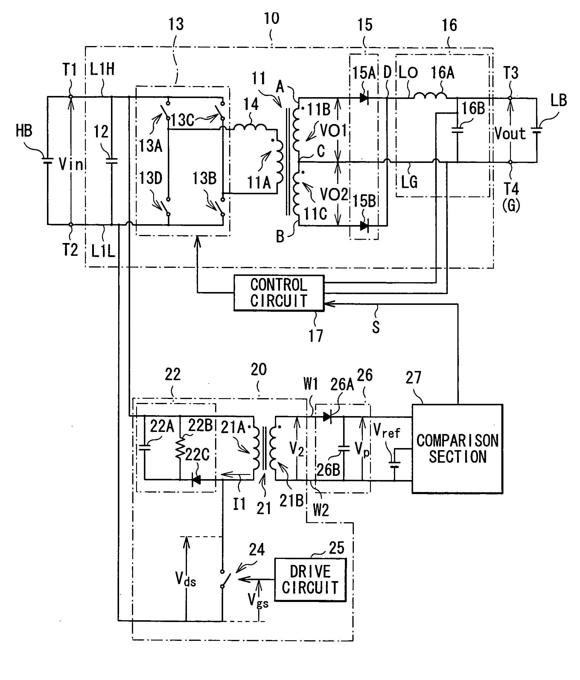
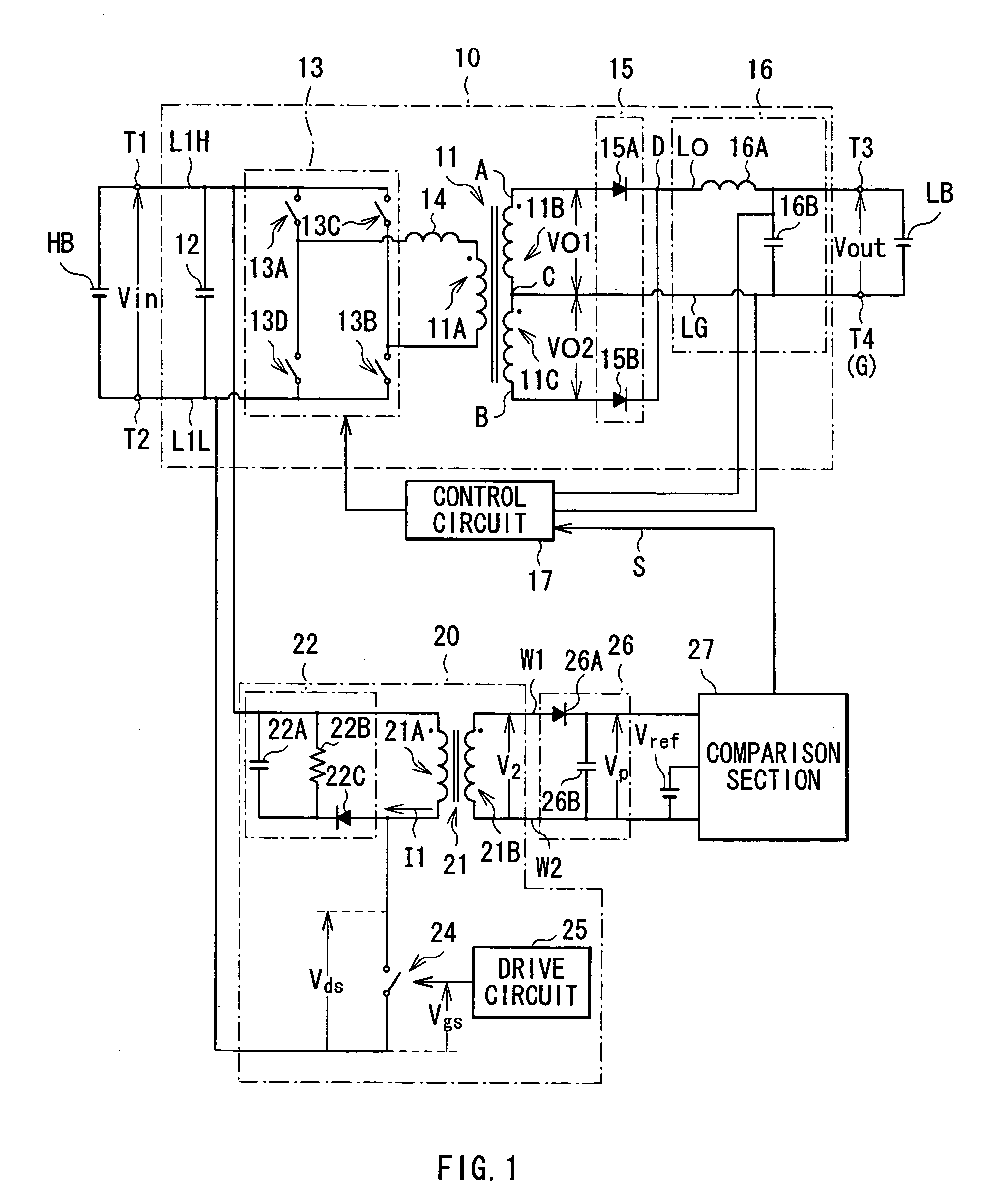
[0055]FIG. 1 shows a configuration of a switching power supply unit according to a first embodiment of the invention. The switching power supply unit functions as a DC-DC converter of converting a high DC input voltage Vain supplied from a high-voltage battery HB (first power supply) into a relatively low DC output voltage Vout, and supplying the voltage Vout to a low-voltage battery LB. (second power supply), and is a switching power supply unit of which the secondary side is in center-tap cathode common connection as will be described later.

[0056] The switching power supply unit includes a power supply main section 10, a voltage detection section 20 (voltage detection circuit) being connected in parallel with the power supply main section 10, a holding section 26 being connected to the voltage detection section 20, a comparison section 27 being connected to the holding section 26, and a control circuit 17 being connected to the power supply main section 10.

[0057] First, a config...

second embodiment

[0101] Next, a second embodiment of the invention will be described.

[0102]FIG. 7 shows a circuit configuration of a switching power supply unit according to a second embodiment. In the figure, the same components as those shown in FIG. 1 are marked with the same references, and appropriately omitted to be described. In the switching power supply unit, a voltage detection section 30 is provided instead of the voltage detection section 20.

[0103] The voltage detection section 30 (voltage detection circuit) has a transformer 31 (voltage detection transformer), regeneration circuit 32, two switching elements 341 and 342, two drive circuits 351 and 352 respectively corresponding to the switching elements 341 and 342, and a pair of detection signal lines W3 and W4.

[0104] As the transformer 21 in the first embodiment, the transformer 31 includes a primary winding 31A (first transformer coil) and a secondary winding 31B (second transformer coil), which is a double forward transformer in w...

third embodiment

[0124] Next, a third embodiment of the invention will be described.

[0125]FIG. 15 shows a configuration of a switching power supply unit according to a third embodiment. The switching power supply unit functions as a DC-DC converter of converting a high DC input voltage Vin supplied from a high-voltage battery HB (first power supply) into a relatively low DC output voltage Vout, and supplying the voltage Vout to a low-voltage battery LB. (second power supply), and is a switching power supply unit of which the secondary side is in center-tap cathode common connection as will be described later.

[0126] The switching power supply unit includes a power supply main section 10, voltage detection section 40 being connected in parallel with the power supply main section 10, a holding section 46 being connected to the voltage detection section 40, comparison section 47 being connected to the holding section 46, and control circuit 19 being connected to the power supply main section 10.

[0127...


PUM


Abstract

A switching power supply unit is provided, in which a DC input voltage can be detected even if switching operation of the power supply unit is stopped. A switching power supply unit includes: a power supply main section switching a DC input voltage inputted from a first power supply to convert the DC input voltage into an AC voltage, and outputting a DC output voltage into a second power supply, the DC output voltage being obtained by transforming and rectifying the AC voltage; and a voltage detection section having a voltage detection transformer, one or more switching elements, and detection signal lines. The voltage detection transformer includes a first transformer coil as a primary winding being intermittently applied with the DC input voltage in response to on / off of the switching element, and a second transformer coil as a secondary winding being connected to the detection signal lines.

Description

BACKGROUND OF THE INVENTION [0001] 1. Field of the Invention [0002] The present invention relates to a switching power supply unit being configured to produce switching output obtained by switching DC input voltage at an output winding of a voltage conversion transformer, and a voltage detection circuit for use in such a switching power supply unit. [0003] 2. Description of the Related Art [0004] Generally, a hybrid electric vehicle is equipped with a low voltage battery of outputting a low DC voltage such as about 12 V as a power supply for driving in-vehicle instruments such as a wiper, a headlight, a room light, an audio instrument, an air conditioner, and various measuring instruments, and equipped with a high voltage battery of outputting a high DC voltage such as about 400 V as a power supply for driving a motor. Typically, such a low voltage battery is charged by rectifying an AC output voltage from an AC generator driven by using rotation of an engine to obtain a high DC vol...

Claims


Application Information

Patent Timeline
IPC IPC(8): H02M3/335H02J1/10
CPCH02M3/337H02M3/33573H02M3/01
Inventor TANAKA, KATSUAKI
Owner TDK CORPARATION
Why Eureka
Try Eureka