Flexible flat cable for transmitting high-frequency signals

Inactive Publication Date: 2019-10-03
BELLWETHER ELECTRONIC CORP
View PDF3 Cites 1 Cited by
  • Summary
  • Abstract
  • Description
  • Claims
  • Application Information

AI Technical Summary

Benefits of technology

The present patent provides a flexible flat cable for transmitting high-frequency signals. It has a coordinated insulated partition layer and metallic shielding layer that adjust different high-frequency characteristics to enhance stability and achieve a thinning effect. The sealing section provides a complete shielding layer to block electromagnetic interference and reduce RF interference propagation. Overall, this cable provides improved high-frequency signal transmission while being flexible, efficient, and easy to produce.

Problems solved by technology

Therefore, it has become an important issue to improve an effusion of internal noise, block the penetration of external noise and reduce the propagation of radio frequency interference.
However, the metal layer formed by such a manner has an uneven thickness, even affecting the flatness.
Further, a distance between the metal plating layer and the conductor is also uneven, and the resistance controlling is unstable, which cannot achieve better high-frequency characteristics.
However, the surrounding manner requires manpower, so that the conventional cable is not able to adapt mass production.
In the high-frequency field, the impedance of the stacked part of the metal layer is hard to be well controlled.
When the metal layer is bent, partial peeling-off is easily happened, which is not viewable and results in bad high-frequency characteristics.
Moreover, in the method of surrounding the metallic shielding layer around the flexible flat cable it is not easy to control a distance between the metallic shielding layer and signal conductors for transmitting high-frequency signals, which will cause an unpredictable change of high-frequency characteristics.
Even though two metal layers are respectively disposed at two sides of the flexible flat cable, to avoid the stacking problem of the metallic shielding layer, the lateral edges of the flexible flat cable still lack proper shielding, and may result in a penetration of electromagnetic interference and a propagation of RF (Radio Frequency) interference.

Method used


Image

  • Flexible flat cable for transmitting high-frequency signals
  • Flexible flat cable for transmitting high-frequency signals
  • Flexible flat cable for transmitting high-frequency signals

Examples


first embodiment

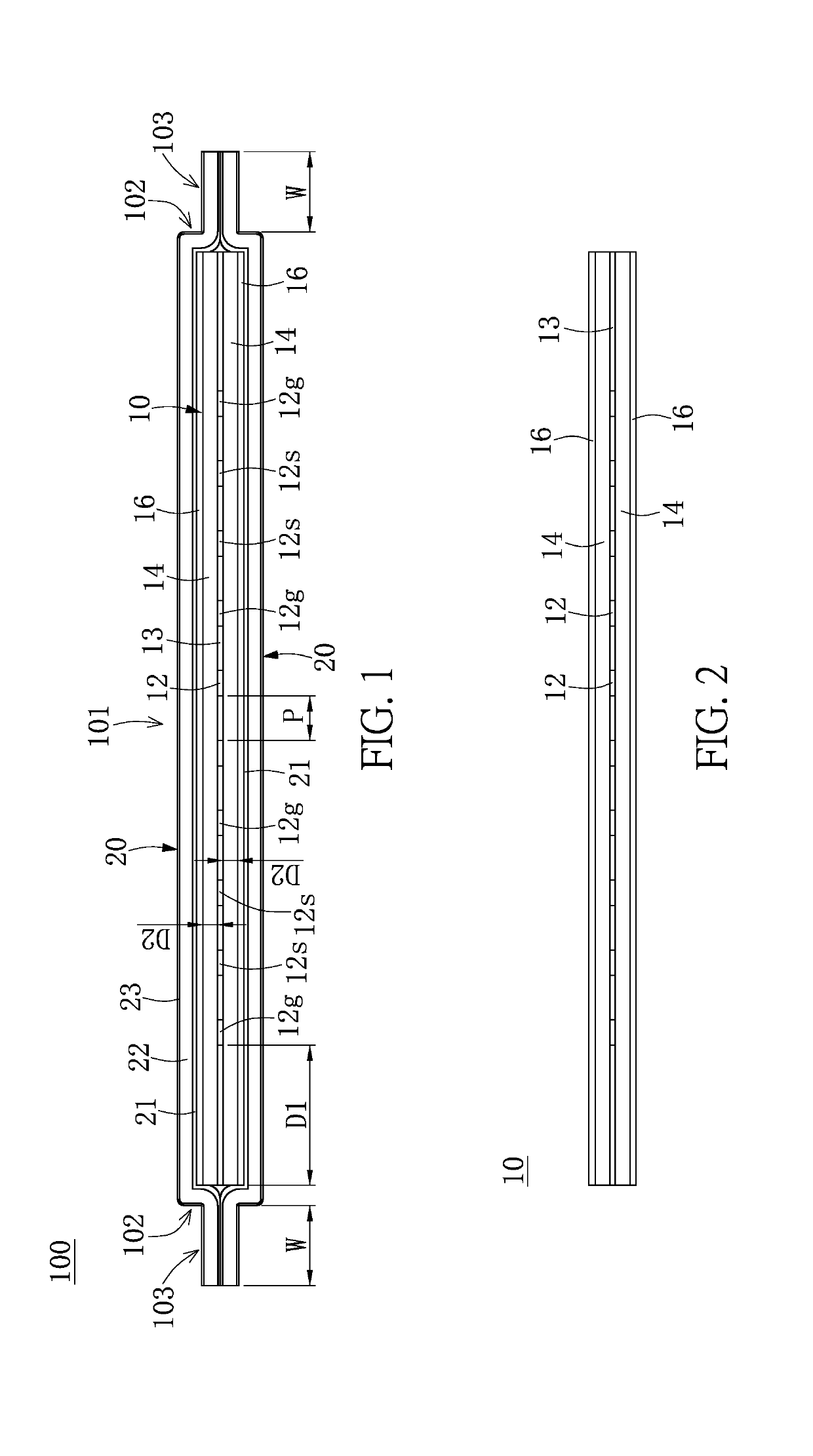
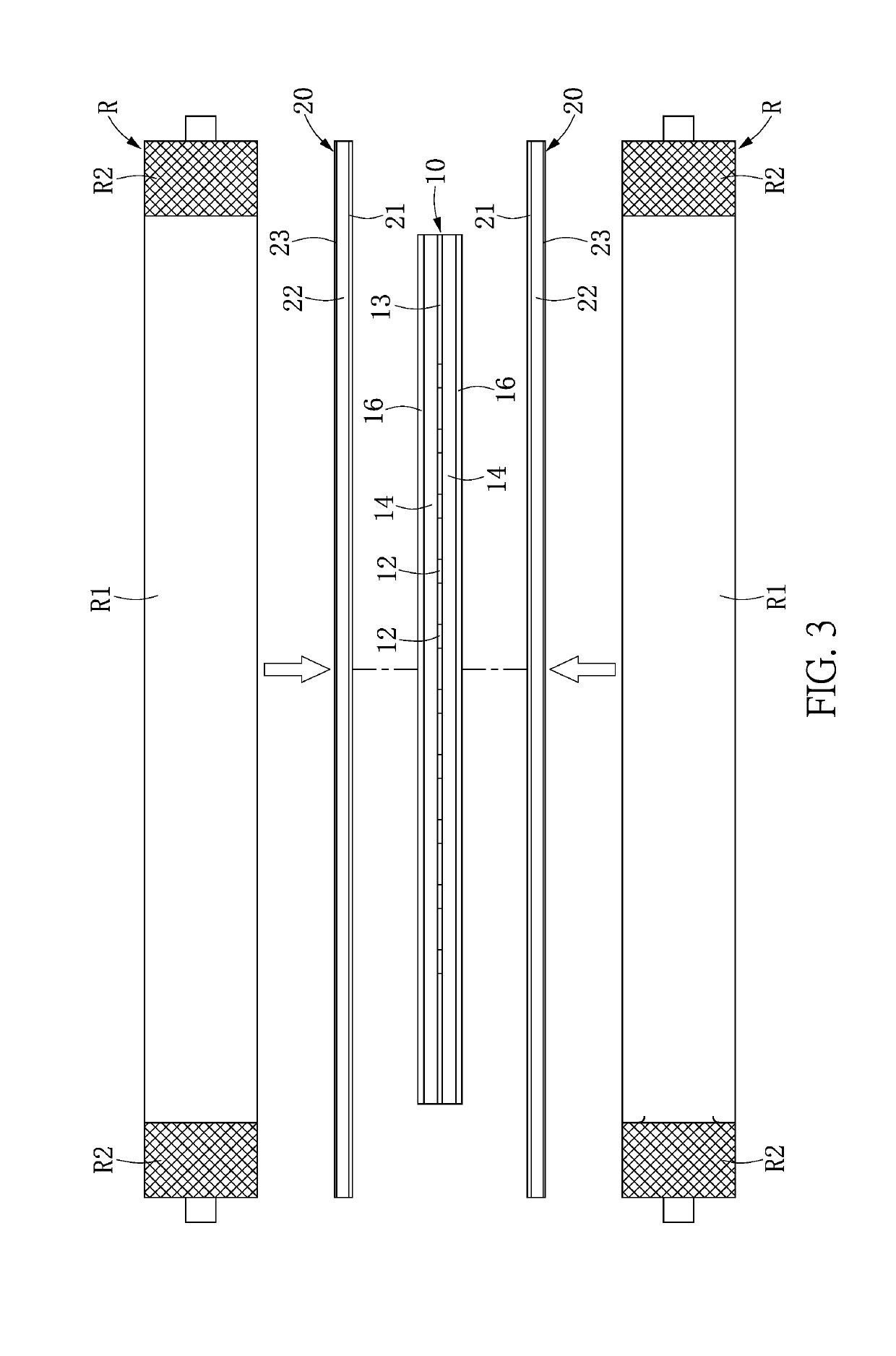
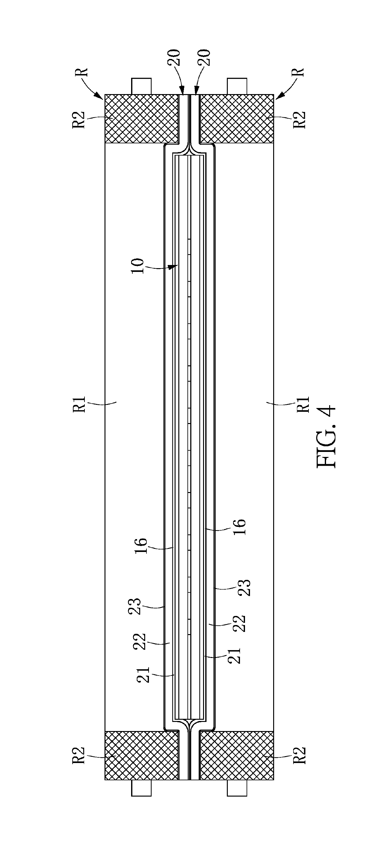
[0021]Reference is made to FIG. 1, which is a front view of a flexible flat cable for transmitting high-frequency signals of the present disclosure. The present disclosure provides a flexible flat cable 100 for transmitting high-frequency signals, or a flexible flat cable, which includes an inner flat cable 10 and a pair of shielding composite layers 20. In addition, the flexible flat cable 100 has a main section 101, two connecting sections 102, and two sealing sections 103 which extended in a horizontal direction, (or called a traverse direction) as shown in FIG. 1. The two connecting sections 102 are extended from two sides of the main section 101. The two sealing sections 103 are respectively extended from the two connecting sections 102.

[0022]The inner flat cable 10 is disposed in the main section 101. The inner flat cable 10 has a plurality of conductors 12, an insulated glue layer 13, a pair of insulated partition layers 14, and a pair of metallic shielding layers 16. The con...

second embodiment

[0036]Referring to FIG. 5, which is a front view of the flexible flat cable for transmitting high-frequency signals of another embodiment according to the present disclosure. Different from the above embodiment, according to the flexible flat cable for transmitting high-frequency signals 100a of this embodiment, a width of the metallic shielding layer 16a is smaller than a width of the insulated partition layer 14. In addition, the metallic shielding layers 16a are arranged are an upper side and a lower side of the signal conductors 12s, which are used for shielding the conductors of transmitting high-frequency signals.

[0037]Specifically, this embodiment has two metallic shielding layers 16a disposed on the upper side of the insulated partition layer 14, which are correspondingly to shield four of the conductors 12, and another two metallic shielding layers 16a disposed on the lower side of the insulated partition layer 14, which are correspondingly to shield four of the conductors ...


PUM


Abstract

A flexible flat cable for transmitting high-frequency signals includes an inner flat cable and a pair of shielding composite layers, which are divided into a main section, two connecting sections, and two sealing sections. The inner flat cable is disposed in the main section, and includes a plurality of conductors, an insulated glue layer, a pair of insulated partition layers and a pair of metallic shielding layers. The pair of insulated partition layers are disposed at two sides of the conductors and are affixed oppositely. The pair of metallic shielding layers are disposed at outer sides of the pair of insulated partition layers. Each shielding composite layer has a width larger than a width of the inner flat cable, and includes an outer shielding layer and a conductive glue layer having one part affixed to the inner flat cable and another part affixed to each other.

Description

CROSS-REFERENCE TO RELATED PATENT APPLICATION[0001]This application claims the benefit of priority to Taiwan Patent Application No. 107204011, filed on Mar. 28, 2018. The entire content of the above-identified application is incorporated herein by reference.[0002]Some references, which may include patents, patent applications, and various publications, may be cited and discussed in the description of this disclosure. The citation and / or discussion of such references is provided merely to clarify the description of the present disclosure and is not an admission that any such reference is “prior art” to the disclosure described herein. All references cited and discussed in this specification are incorporated herein by reference in their entireties and to the same extent as if each reference was individually incorporated by reference.FIELD OF THE DISCLOSURE[0003]The present disclosure relates to a flexible flat cable for transmitting high-frequency signals, and more particularly to a s...

Claims


Application Information

Patent Timeline
IPC IPC(8): H01B7/08H01B13/22
CPCH01B13/22H01B7/0838H01B7/0861H01B7/0018
Inventor LEE, HSING-YUTAN, JIE-YAU
Owner BELLWETHER ELECTRONIC CORP
Why Eureka
Try Eureka