
Polishing composition, method for producing polishing composition, and polishing method

a technology of polishing composition and composition, which is applied in the direction of manufacturing tools, lapping machines, other chemical processes, etc., can solve the problems of many scratches on the substrate surface and inability to achieve a sufficient polishing speed, and achieve the effect of improving the polishing speed of the substra

Inactive Publication Date: 2019-09-26
FUJIMI INCORPORATED
View PDF0 Cites 2 Cited by
  • Summary
  • Abstract
  • Description
  • Claims
  • Application Information

AI Technical Summary

Benefits of technology

The patent text describes a problem in polishing objects that contain oxygen and silicon atoms. Aqueous chemical mechanical polishing compositions can improve polishing speed, but cause many scratches on the substrate surface. Chemical mechanical polishing compositions can reduce scratches, but cannot achieve a sufficient polishing speed. The invention aims to solve this contradiction by providing a polishing composition that can polish an object at a high speed while reducing scratches on the surface.

Problems solved by technology

However, the aqueous chemical mechanical polishing composition described in JP 2001-507739 A (corresponding to U.S. Pat. No. 5,759,917 B) improves the polishing speed of the substrate, but causes many scratches on the substrate surface.
Additionally, the chemical mechanical polishing composition described in JP 2015-063687 A (corresponding to U.S. Pat. No. 9,012,327 B) reduces scratches on the substrate surface, but cannot achieve a sufficient polishing speed.

Method used


Image

  • Polishing composition, method for producing polishing composition, and polishing method

Examples


example 1

[0099]Polishing composition 2 was prepared in the same manner as in Comparative Example 1, except that abrasive grains 2 obtained by hydrothermal treatment of the abrasive grains 1 under the following conditions. More specifically, 1 kg of the abrasive grains 1 was charged into an autoclave with a band heater (TAS-1, manufactured by Taiatsu Techno Corporation) (silica concentration 19.5% by mass, pH 7.3). In this apparatus, the temperature is controlled with a band heater in absolute contact with the container, and heat is uniformly applied to the sample under stirring in the container. Hydrothermal treatment was carried out by programmed operation under the following conditions: the starting point was room temperature (25° C.), the temperature rising rate was 1.75° C. / minute, the maximum temperature was 160° C., the maximum temperature (160° C.) was kept for 1 hour and 45 minutes, and the pressure at the maximum temperature (160° C.) was 0.63 MPa. The abrasive grains after completi...

example 2

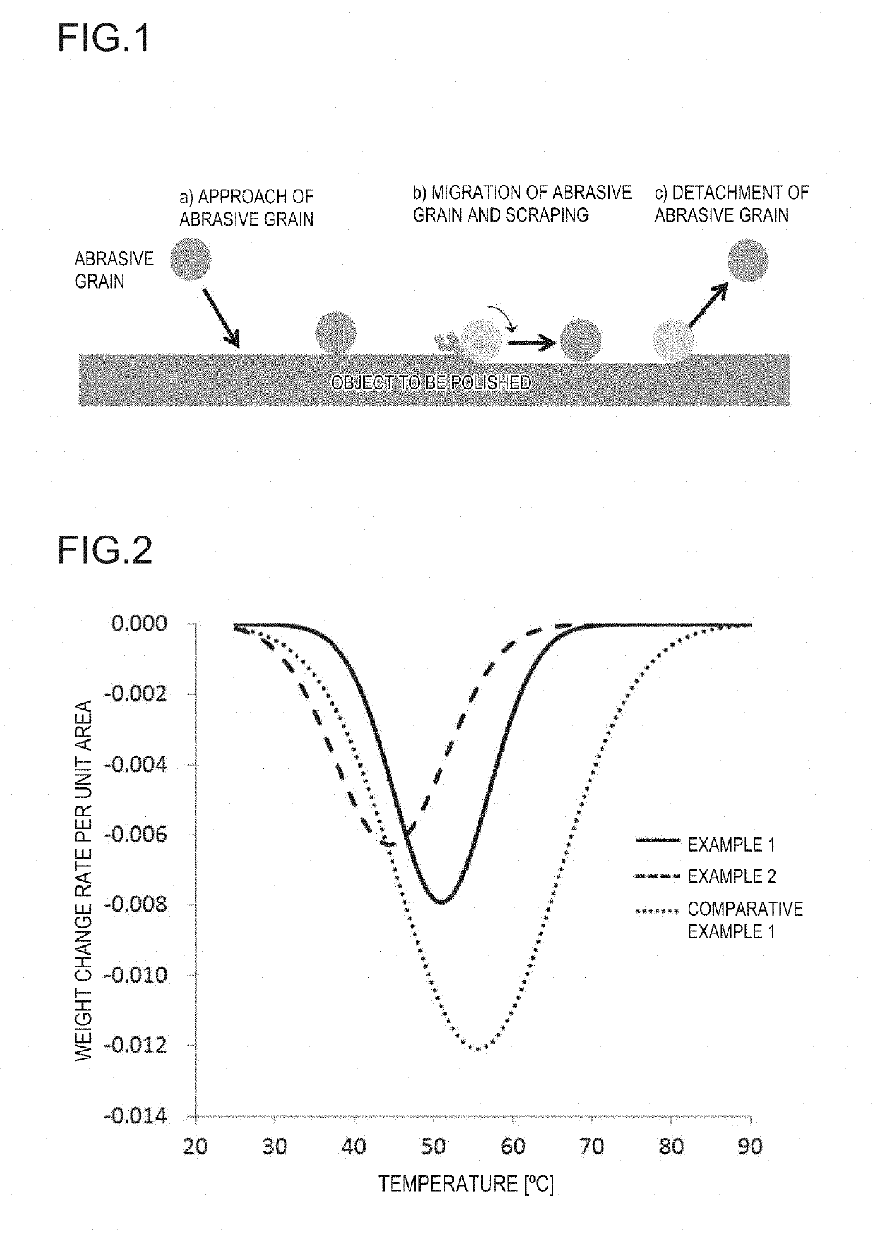
[0103]In Comparative Example 2, lactic acid was added as a pH adjusting agent so as to adjust the pH of the polishing composition to 4.0, thereby preparing a polishing composition. A polishing composition 4 was prepared in the same manner as in Comparative Example 2, except that the above-described operation. FIG. 2 depicts the weight change rate distribution curve of the abrasive grains 3 (Example 2) obtained by thermogravimetric measurement.

[0104]The polishing composition obtained above was evaluated for the polishing speed and defects (number of scratches) according to the following method. These results are given in Table 1. In Table 1, “TEOS RR” means the polishing speed.

[0105][Polishing Speed]

[0106]Using the polishing compositions obtained above, the polishing speed (TEOS RR) during polishing of an object to be polished (TEOS substrate) under the following polishing conditions was measured.

[0107](Polishing Conditions)

[0108]Polishing machine: compact desktop polisher (manufactu...


PUM


Abstract

The present invention provides a polishing composition which polishes an object to be polished at a high polishing speed and with less scratches (defects).The present invention is a polishing composition including silica having a maximum peak temperature of 30° C. or higher and 53° C. or lower in a weight change rate distribution curve obtained by thermogravimetric measurement in a range of 25° C. or higher and 250° C. or lower, and having a pH at 25° C. of less than 6.0.

Description

TECHNICAL FIELD[0001]The present invention relates to a polishing composition, a method for producing a polishing composition, and a polishing method.BACKGROUND ART[0002]In recent years, along with multilayer wiring of semiconductor substrate surfaces, so-called chemical mechanical polishing (CMP), which is a technique of flattening a semiconductor substrate by polishing, is used in the production of devices. CMP is a method for flatting the surface of an object to be polished such as a semiconductor substrate using a polishing composition (slurry) including abrasive grains such as silica, alumina, and ceria, an anticorrosive, and a surfactant, wherein the object to be polished is, for example, silicon, polysilicon, a silicon oxide film (silicon oxide), silicon nitride, a wire or a plug made of a metal or the like.[0003]For example, as a CMP slurry for polishing a substrate including oxygen atoms and silicon atoms such as silicon oxide, JP 2001-507739 A (corresponding to U.S. Pat. N...

Claims


Application Information

Patent Timeline
IPC IPC(8): C09G1/02B24B37/04C09K3/14H01L21/3105H01L21/306H01L21/321
CPCH01L21/30625H01L21/31053B24B37/044C09K3/1463H01L21/3212C09G1/02B24B37/00C09K3/14H01L21/304
Inventor SUZUKI, SHOTAIZAWA, YOSHIHIRO
Owner FUJIMI INCORPORATED
Learn More