Apparatus and Method For Laser Processing A Material

a material processing and apparatus technology, applied in the direction of cladding optical fibre, manufacturing tools, instruments, etc., can solve the problems of limited benefit, inability to optimize process parameters for all metal types and thicknesses, and similar limitations of other material processing equipment, such as welding and marking

Pending Publication Date: 2019-08-29
SPI LASERS UK
View PDF4 Cites 4 Cited by
  • Summary
  • Abstract
  • Description
  • Claims
  • Application Information

AI Technical Summary

Benefits of technology

The invention is about a device that can adjust the properties of laser beams to improve cutting and material processing. By varying the squeezing force and selecting different optical fibers, the device can control the beam radius and effective numerical aperture, and change the output beam profile. This allows for better optimization of material processes and higher quality cutting. Additionally, the device can include a vibrating element to remove laser speckle from the beam.

Problems solved by technology

This has limited benefit since a laser having constant laser beam quality will have a fixed relationship between focal spot size and divergence which works in the opposite way to that desired by the cutting process regimes.
It is therefore not possible to optimize process parameters for all metal types and thicknesses.
Similar limitations arise with other material processing equipment, such as welding, marking, and additive manufacturing.

Method used


Image

  • Apparatus and Method For Laser Processing A Material
  • Apparatus and Method For Laser Processing A Material
  • Apparatus and Method For Laser Processing A Material

Examples


example 1

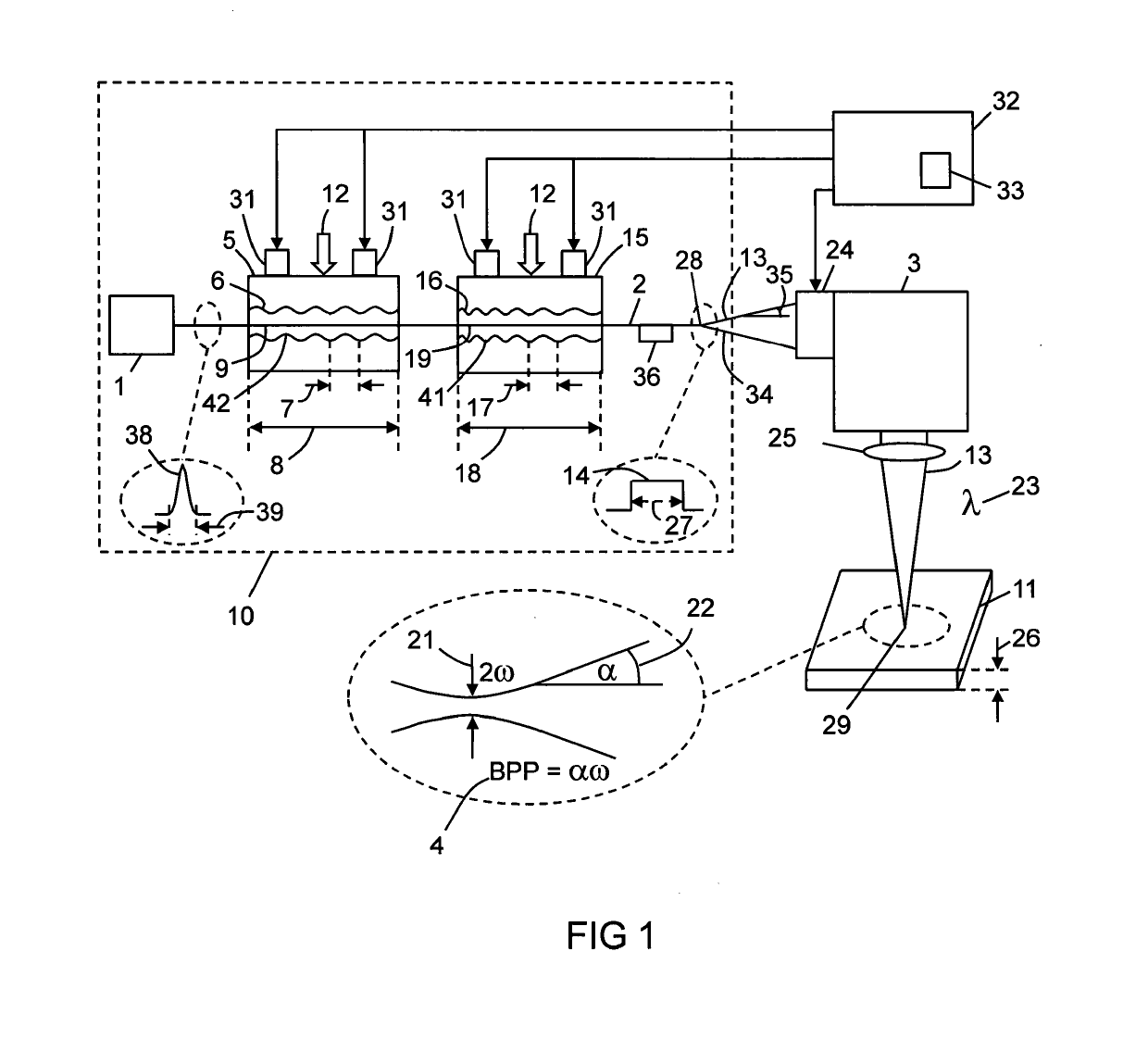
[0123]FIG. 20 shows a first Example of the invention. The squeezing mechanism 5 shown in FIG. 1 was applied to the first optical fibre 90 of FIG. 11. The core 91 supported the fundamental mode 121 of FIG. 12 and the second order mode 122 of FIG. 13. The fundamental mode 121 propagated in the core 91 as indicated above and below the first optical fibre 90 at point A. The core 91 had a diameter 92 of order 15 μm and a refractive index 96 which was greater than the cladding index 99 by 0.0034. The squeezing mechanism 5 had a pitch 7 which matched the difference in the effective indices 97 and 98 of the optical modes 121 and 122 such that the pitch 17=2π / Δβ. By adjusting the squeezing force 12 applied by the squeezing mechanism 5, the laser radiation 13 output by the first optical fibre 90 could be switched between the fundamental mode 121 and the second order mode 122 as indicated above and below the first optical fibre 90 at point B of FIG. 20 respectively. It was also possible to swi...

example 2

[0127]FIG. 21 shows a second Example of the invention in which the first optical fibre 90 of the First Example has been replaced by the optical fibre 140. The squeezing mechanism 5 shown in FIG. 1 was applied to the fibre 140 shown in FIG. 14. The core 91 had a diameter 92 of approximately 15 um and a refractive index 96 which was greater than the cladding refractive index 99 by 0.0034. The core 91 could support the fundamental mode 121 having the effective refractive index 97. The four satellite cores 141 each had a diameter 143 of 6.6 μm, a refractive index 142 greater than the cladding refractive index 99 by 0.003, and an outer edge to outer distance 149 of 36.6 μm. The satellite cores 141 could propagate mode(s) 151 having an effective refractive index 143. The squeezing mechanism 5 had a pitch 7 designed to match the difference in the effective refractive indices 97 and 143 such that the pitch 7=2π / Δβ. As indicated in FIG. 21, by adjusting the squeezing force 12 applied by the ...

example 3

[0129]FIG. 22 shows a third Example of the invention in which the second optical fibre 140 of the first Example has been replaced by the second optical fibre 160 of FIG. 16, and the third optical fibre 180 of the first Example has been replaced by the third optical fibre 190 described with reference to FIG. 19. The design of the first optical fibre 90 was the same as described with reference to the first Example and FIG. 20.

[0130]The first optical fibre 90 was spliced to the second optical fibre 160 shown in FIG. 16. The central core 91 of the second optical fibre 160 was the same design as the core 91 of the first optical fibre 90. The ring core 161 had an outer diameter 169 of 40 μm, a thickness 164 of 5 μm, and a refractive index 162 that was greater than the cladding refractive index 99 by 0.0026. When the squeezing mechanism 5 was adjusted such that the output of the first optical fibre 90 was the fundamental mode 121, the fundamental mode 121 coupled successfully to the core 9...


PUM

PropertyMeasurementUnit
pressureaaaaaaaaaa
diameteraaaaaaaaaa
pressuresaaaaaaaaaa

Abstract

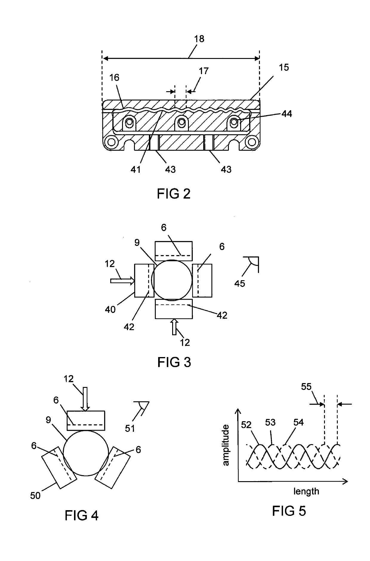
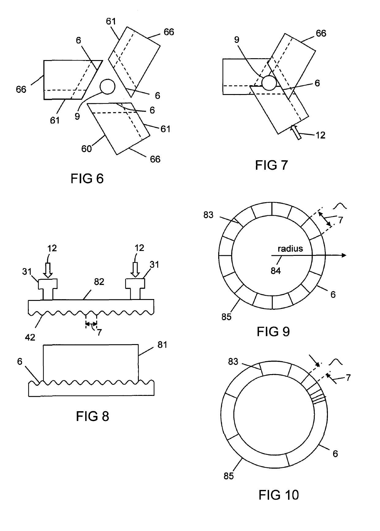
Apparatus (10) for laser processing a material (11), which apparatus comprises a laser (1) and a beam delivery cable (2), wherein: the laser (1) is connected to the beam delivery cable (2); the beam delivery cable (2) is configured to transmit laser radiation (13) emitted from the laser (1), and the laser radiation (13) is defined by a beam parameter product (4); and the apparatus (10) is characterized in that: the apparatus (10) includes at least one squeezing mechanism (5) comprising a periodic surface (6) defined by a pitch (7); a length (8) of optical fibre (9) that forms part of the laser (1) and / or the beam delivery cable (2) is located adjacent to the periodic surface (6); and the squeezing mechanism (5) is configured to squeeze the periodic surface (6) and the length (8) of the optical fibre (9) together with a squeezing force (12); whereby the beam parameter product (4) is able to be varied by adjusting the squeezing force (12).

Description

FIELD OF INVENTION[0001]This invention relates to an apparatus and method for laser processing a material.BACKGROUND TO THE INVENTION[0002]Laser cutting of steel is achieved by directing the laser beam to the work-piece via a process head which has optics for collimating and focusing the laser beam and a conical copper nozzle to provide a high pressure gas jet which is co-axial with the beam. The basic cutting operation involves the laser beam heating and melting the metal sheet work-piece and the gas jet, known as the assist gas jet, blowing the molten material out of the bottom of the cut-zone. The cutting head is moved over the sheet metal whilst maintaining a constant distance between the nozzle tip and the work-piece surface. The cutting head is moved in a programmed path to create the desired sheet metal profile.[0003]In the case of cutting stainless steel, it is typical to use an inert assist gas. This avoids the creation of metal oxides on the cut-edge faces of the work-piec...

Claims


Application Information

Patent Timeline
Patent Type & Authority Applications(United States)
IPC IPC(8): B23K26/38B23K26/073B23K26/06B23K26/08B23K26/142G02B6/02G02B27/48
CPCB23K26/38B23K26/073B23K26/0665B23K26/0648G02B27/48B23K26/142G02B6/02071G02B6/02042B23K26/0876B23K26/70B23K26/702B23K26/06B23K26/20B23K26/34
Inventor MALINOWSKI, ANDREWCODEMARD, ANDRÈ CHRISTOPHEZERVAS, MIKHAIL NICKOLAOSHARRISON, PAUL MARTINGREENWOOD, MARK
Owner SPI LASERS UK
Why Eureka
Try Eureka