
Structure with embedded memory device and contact isolation scheme

a technology of embedded memory and contact isolation, which is applied in the direction of solid-state devices, transistors, basic electric elements, etc., can solve the problems of high variation of device dimensions and device performance, limited and inaccurate control of passive devices, and device parameters may run out of specification

Active Publication Date: 2019-05-30
TAIWAN SEMICON MFG CO LTD
View PDF4 Cites 1 Cited by
  • Summary
  • Abstract
  • Description
  • Claims
  • Application Information

AI Technical Summary

Benefits of technology

The present patent application claims priority to a U.S. Provisional Patent Application No. 62 / 592,810 filed Nov. 30,2017, and describes a structure and method for making an integrated circuit with a passive device, such as a resistor or a capacitor, that are formed using various fabrication technologies. The technical effects of the patent include addressing issues with existing technologies that have limited and inaccurate control over the dimensions of the passive device, resulting in high variations in device performance and reliability issues. The present disclosure provides a solution to improve the accuracy and control of the dimensions of the passive device, allowing for better performance and reliability of the integrated circuit.

Problems solved by technology

Those technologies have limited and inaccurate control to dimensions of the passive device, which causes high variations of the device dimensions and the device performance as well.
In some cases, the device parameters may run out of the specification and fail the circuit.
Furthermore, the existing methods are hard to be implemented in the advanced technology nodes due to high processing variation and small feature sizes.
Especially, when the semiconductor technologies move forward to advanced technology nodes with smaller feature sizes, such as 7 nm or less, the misalignments have less tolerance and may cause leakage, short, opening or other failure defects or reliability issue.

Method used


Image

  • Structure with embedded memory device and contact isolation scheme
  • Structure with embedded memory device and contact isolation scheme
  • Structure with embedded memory device and contact isolation scheme

Examples


Embodiment Construction

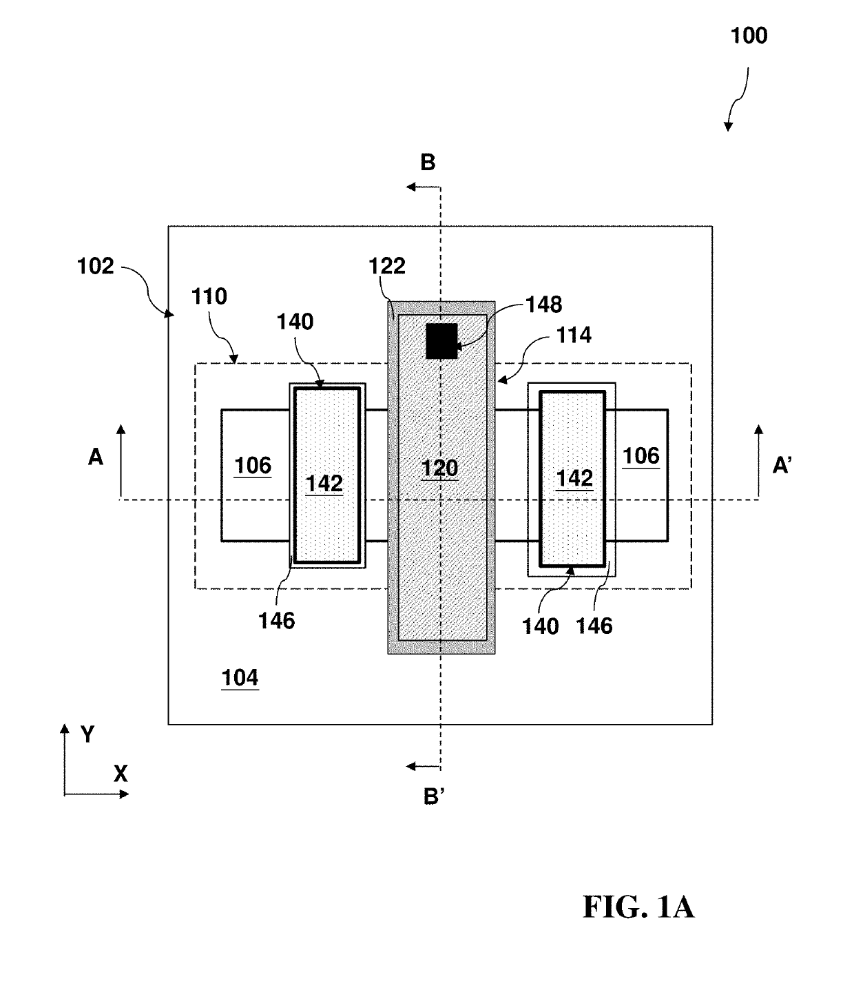
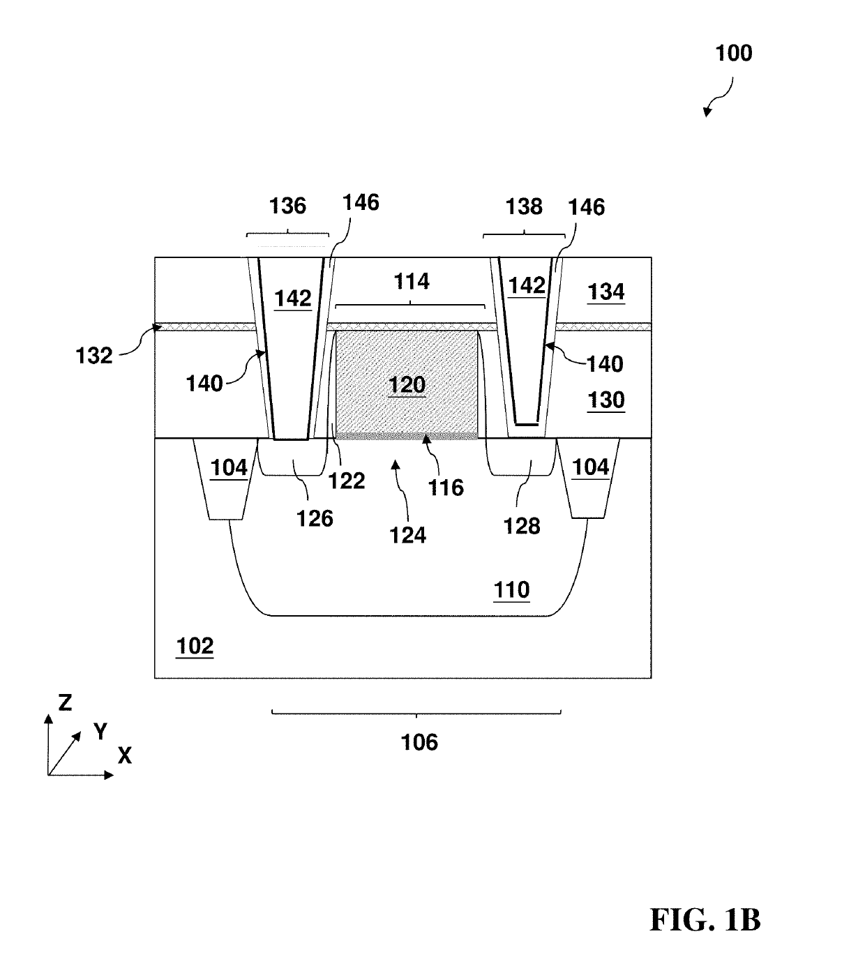
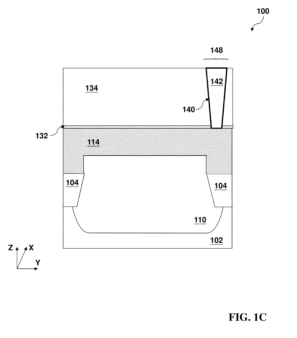
[0027]The following disclosure provides many different embodiments, or examples, for implementing different features of the invention. Specific examples of components and arrangements are described below to simplify the present disclosure. These are, of course, merely examples and are not intended to be limiting. For example, the formation of a first feature over or on a second feature in the description that follows may include embodiments in which the first and second features are formed in direct contact, and may also include embodiments in which additional features may be formed between the first and second features, such that the first and second features may not be in direct contact. In addition, the present disclosure may repeat reference numerals and / or letters in the various examples. This repetition is for the purpose of simplicity and clarity and does not in itself dictate a relationship between the various embodiments and / or configurations discussed. It is to be understo...


PUM


Abstract

The present disclosure provides a method of fabricating an integrated circuit in accordance with some embodiments. The method includes forming a source and a drain on a fin active region of a semiconductor substrate; depositing an interlayer dielectric (ILD) layer on the source and drain; patterning the ILD layer to form a first contact hole and a second contact hole aligning with the source and drain, respectively; forming a dielectric material layer in the first contact hole; and forming a first conductive feature and a second conductive feature in the first and second contact holes, respectively.

Description

PRIORITY DATA[0001]This application claims priority to U.S. Provisional Patent Application Ser. No. 62 / 592,810 filed Nov. 30, 2017, the entire disclosure of which is hereby incorporated herein by reference.BACKGROUND[0002]In an integrated circuit, an integrated circuit pattern can be formed on a substrate using various fabrication technologies that include photolithography patterning, etching, deposition and ion implantation. Thus formed integrated circuits include various devices, such as field-effect transistor, diode, bipolar transistor, imaging sensor, light-emitting diode, memory cell, resistor, and capacitor, integrated together. A memory device may include a passive device, such as a capacitor or a resistor coupled with other devices, such as a field-effect transistor. In the existing technologies, a passive device, such as a resistor, is formed through various semiconductor technologies that include etching. Those technologies have limited and inaccurate control to dimension...

Claims


Application Information

Patent Timeline
IPC IPC(8): H01L27/06H01L49/02H01L21/768H01L23/522H01L21/311H01L27/108H01L27/112H01L27/24H01L29/78
CPCH01L27/0629H01L28/60H01L28/20H01L21/76802H01L21/76831H01L21/76816H01L23/5226H01L23/5223H01L23/5228H01L21/76846H01L21/76844H01L27/11206H01L27/10811H01L27/2436H01L29/785H01L21/31116H01L21/31144H01L21/823431H01L21/76877H10B20/25H01L28/91H01L27/0738H01L27/0733H01L29/41791H01L29/66795H01L23/485H10B12/36H10B12/30H10B12/03H10B12/056H01L21/324H01L21/76813H01L21/304H10B12/312H10B20/20H10B63/30
Inventor MENG, FAN-SHUENCHEN, HUANG-KUIHSIEH, MIN-YANN
Owner TAIWAN SEMICON MFG CO LTD
Learn More