High Brightness Solid State Illumination System for Fluorescence Imaging and Analysis

Active Publication Date: 2019-04-25
EXCELITAS CANADA
View PDF2 Cites 3 Cited by
  • Summary
  • Abstract
  • Description
  • Claims
  • Application Information

AI Technical Summary

Benefits of technology

The patent is about a new LED light source that uses a standard white light emitting LED and a yellow phosphor layer to increase the output in the green, yellow, and amber regions of the spectrum. This LED light source is controlled by a laser that optically pumps the phosphor layer, resulting in high radiance in the phosphor's emission band. The laser pump can be the same as or different from the LED wavelength, and a solid state laser can be used. The phosphor layer can cover a band from 350 nm to 750 nm, with a focus on the green gap. The invention offers a new way to achieve high brightness output at specific wavelengths used for fluorescence microscopy.

Problems solved by technology

Nevertheless, it is recognized that there are a number of problems associated with conventional lamp technologies, such as short lifetime, temporal variation of the output power, high voltage operation (typically kilovolts are required to strike the lamp), and use of mercury.
The latter is now seen as an environmental hazard and subject to regulations to limit use in numerous countries throughout the world.
Nevertheless, despite technological advances in LED technology, high brightness LED light sources are not available to cover all wavelengths required for illumination systems for fluorescence imaging and analysis.
In particular, the output of LED devices still do not match the radiance of traditional arc-lamps in some regions of the visible spectrum, especially in the 540 nm to 630 nm spectral band, i.e. in the green / yellow / amber range of the visible spectrum.
Emission in this region of the spectrum is fundamentally limited by the lack of availability of semiconductor materials having a suitable band gap to produce light of the required wavelength.
This is a particular problem for fluorescence imaging and analysis which may, for example, require illumination of a biological sample with a relatively narrow band of illumination of a particular wavelength that is absorbed by a selected fluorophore or marker in the substance under test.
However, in view of the “green gap” mentioned above, there are currently no single color, high brightness LEDs commercially available for emission at 545 nm and 575 nm.
This level of power is insufficient for most conventional fluorescence microscopy applications.
By increasing the drive current, some improvement of the light output can be achieved, but fundamentally, the power in this circumstance is limited by the maximum drive current density (i.e. current per unit area) and factors, such as, the LED optical to electrical conversion efficiency, the LED output intensity, the phosphor quantum efficiency, and thermal quenching of both the LED and phosphor, as well as the cooling capacity.
However, the efficiency of such a device would be limited by total internal reflection due to the high index of refraction of Ce:YAG and requires coupling of multiple LEDs to generate output of sufficient brightness, which increases the cost, size, thermal and electrical requirements.
While effective, due to the particular shape and size of the crystal and cooling requirements, this system is currently relatively costly to manufacture.

Method used


Image

  • High Brightness Solid State Illumination System for Fluorescence Imaging and Analysis
  • High Brightness Solid State Illumination System for Fluorescence Imaging and Analysis
  • High Brightness Solid State Illumination System for Fluorescence Imaging and Analysis

Examples


first embodiment

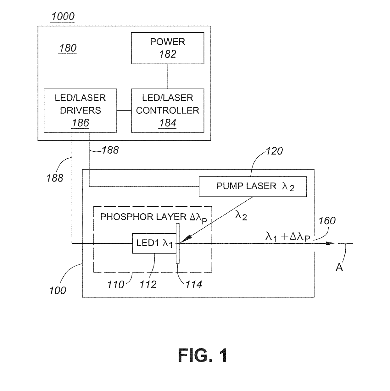
[0069]A schematic diagram showing elements of an illumination system 1000, according to the invention, is shown in FIG. 1. The illumination system 1000 comprises a light source unit or module 100 for providing high brightness illumination for fluorescence illumination and analysis. The light source unit 100 comprises first and second light sources 110 and 120. The first light source 110 comprises an LED 112 (LED1) and a phosphor layer 114, the LED 112 emitting a first wavelength λ1 within an absorption band of the phosphor layer and the phosphor layer 114 emitting broadband light emission of longer wavelength, comprising light in a wavelength band ΔλPHOSPHOR (abbreviated as ΔλP in the Figures). The second light source 120 comprises a laser 120 emitting at a second wavelength λ2, also within an absorption band of the phosphor layer. The illumination system 1000 also comprises drive means or drive unit, i.e. controller / driver 180 comprising a power supply 182, LED / laser controller 184...

second embodiment

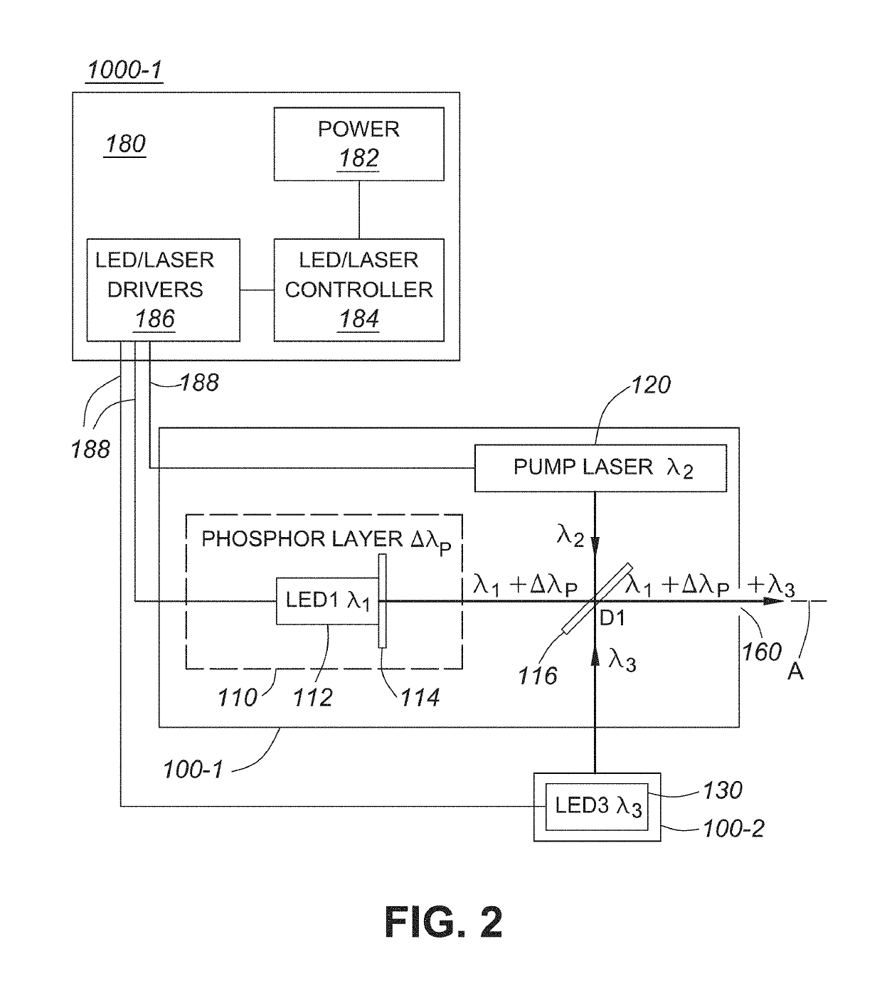
[0074]Thus, a schematic diagram showing elements of an illumination system 1000-1, according to the invention, is shown in FIG. 2. The illumination system 1000-1 comprises a light source unit or module 100-1 for providing high brightness illumination for fluorescence illumination and analysis. The light source unit 100-1 is similar to that shown in FIG. 1, in that it comprises first and second light sources 110 and 120. The first light source 110 comprises an LED 112 (LED1) and a phosphor layer 114, the first LED 112 emitting at a first wavelength λ1 within an absorption band of the phosphor layer and the phosphor layer 114 emitting broadband light emission of longer wavelength, comprising light in a wavelength band ΔλPHOSPHOR (abbreviated as ΔλP in the Figures). The second light source 120 comprises a laser 120, preferably a solid state laser diode, emitting at a second wavelength λ2, also within an absorption band of the phosphor layer. Also provided is a dichroic element, i.e. a ...

third embodiment

[0080]An illumination system 2000 is shown in FIG. 5. The light source unit 200 comprises a first light source module 100-1, comprising first and second light sources 110 and 120, identical to module 100-1 shown in FIG. 2. Like parts are labeled with the same reference numerals in each Figure. Additionally, a second light source module 100-2 comprises two additional light sources 100-2 and 100-3, i.e. a LED or LED arrays 130 and 140 for light emission at other wavelengths. A second dichroic element, i.e. beam-splitter / combiner 118 is provided, which has a band edge selected to combine the output of LED3 and LED4. That is, a LED 130 (LED3) provides light emission at λ3, and a LED 140 (LED4) provides light emission at wavelength λ4. For example, LED3 and LED4 may provide near ultraviolet (near UV) emission and UV emission respectively.

[0081]The drive system 180 is similar to that shown in FIG. 1, comprising a power supply 182, LED / laser controller 184 and LED / laser drivers 186 for dr...


PUM


Abstract

An illumination system includes a phosphor to emit light in a wavelength band ΔλPHOSPHOR, a second light source to emit light at a second wavelength λ2 within an absorption band of the phosphor, a third light source to emit light at a third wavelength λ3 and a fourth light source to emit light at a fourth wavelength λ4. A controller drives the second, third and fourth light sources. A first dichroic optical element: 1) directs light from the phosphor to an optical output of the system, 2) directs light from the third light source to the optical output, and 3) directs light from the fourth light source to the optical output. A second dichroic optical element: 1) directs light from the third light source to the first dichroic optical element, and 2) directs the light from the fourth light source to the first dichroic optical element.

Description

CROSS-REFERENCE TO RELATED APPLICATIONS[0001]This application is a continuation-in-part of co-pending U.S. patent application Ser. No. 15 / 924,943, entitled High Brightness Solid State Illumination System for Fluorescence Imaging and Analysis, which was filed on Mar. 19, 2018, which was a continuation of then co-pending U.S. patent application Ser. No. 14 / 862,492, entitled High Brightness Solid State Illumination System for Fluorescence Imaging and Analysis, which was filed on Sep. 23, 2015, said application is a continuation-in-part (CIP) of U.S. patent application Ser. No. 13 / 897,237, entitled High Brightness Solid States Illumination System for Fluorescence Imaging and Analysis, which was filed on May 17, 2013, which was related to co-pending U.S. patent application Ser. No. 13 / 900,089, filed May 22, 2013, entitled “High Brightness Illumination System and Wavelength Conversion Module for Microscopy and Other Applications”, which claims priority from U.S. patent application Ser. No...

Claims


Application Information

Patent Timeline
IPC IPC(8): G02B27/14G01N21/64
CPCG02B27/141G01N21/6456H01S5/005G01N2201/062H01S5/0071G01N21/6458G01N2021/6419G02B21/16G02B27/0994G02B27/146H01S5/0087
Inventor WANG, YONGCONSTANTINOU, PAULKUK, SOLA ANNE
Owner EXCELITAS CANADA
Why Eureka
Try Eureka