
Vapour Barrier Lamina

Inactive Publication Date: 2019-04-04
PYROTEK PTY LTD
View PDF0 Cites 3 Cited by
  • Summary
  • Abstract
  • Description
  • Claims
  • Application Information

AI Technical Summary

Benefits of technology

The patent text describes a vapor barrier system for cryogenic pipes that includes a moisture-proof foil layer between two layers of protective material. The protective layers help prevent punctures on the foil layer, which improves its tear strength. The system also includes a structural layer to further reinforce the foil layer. The technical effects are improved protection against punctures and increased tear strength, which contribute to the overall reliability and durability of the vapor barrier.

Problems solved by technology

However, the temperature gradient also creates a considerable natural moisture drive towards the cryogenic pipe.
Moisture intrusion into the insulation layers degrades insulation performance, while causing ice build-up.
Additionally, moisture intrusion can cause corrosion of the cryogenic pipe under the insulation layer, which is a significant safety hazard.
The compressors, reducers, expanders, valves and other pipework accessories are significant source of noise.
The noise is detrimental to the structural integrity of the cryogenic pipe, due to vibrations causing fatigue, as well as detrimental to the human working environment.
This is a very labour intensive process referred to as fabrication.
Frequently, the conditions require several alternating thermal and acoustic insulation layers, further increasing fabrication costs.
Additionally, the manual application of each layer on-site is an error source for gaps in the insulation, or the moisture-proof foil, that may lead to moisture intrusion.
This error source is difficult to control at installation, as the cryogenic pipe undergoes significant thermal shrinkage as it cools from ambient temperature to operating temperature.

Method used


Image

  • Vapour Barrier Lamina
  • Vapour Barrier Lamina
  • Vapour Barrier Lamina

Examples


Embodiment Construction

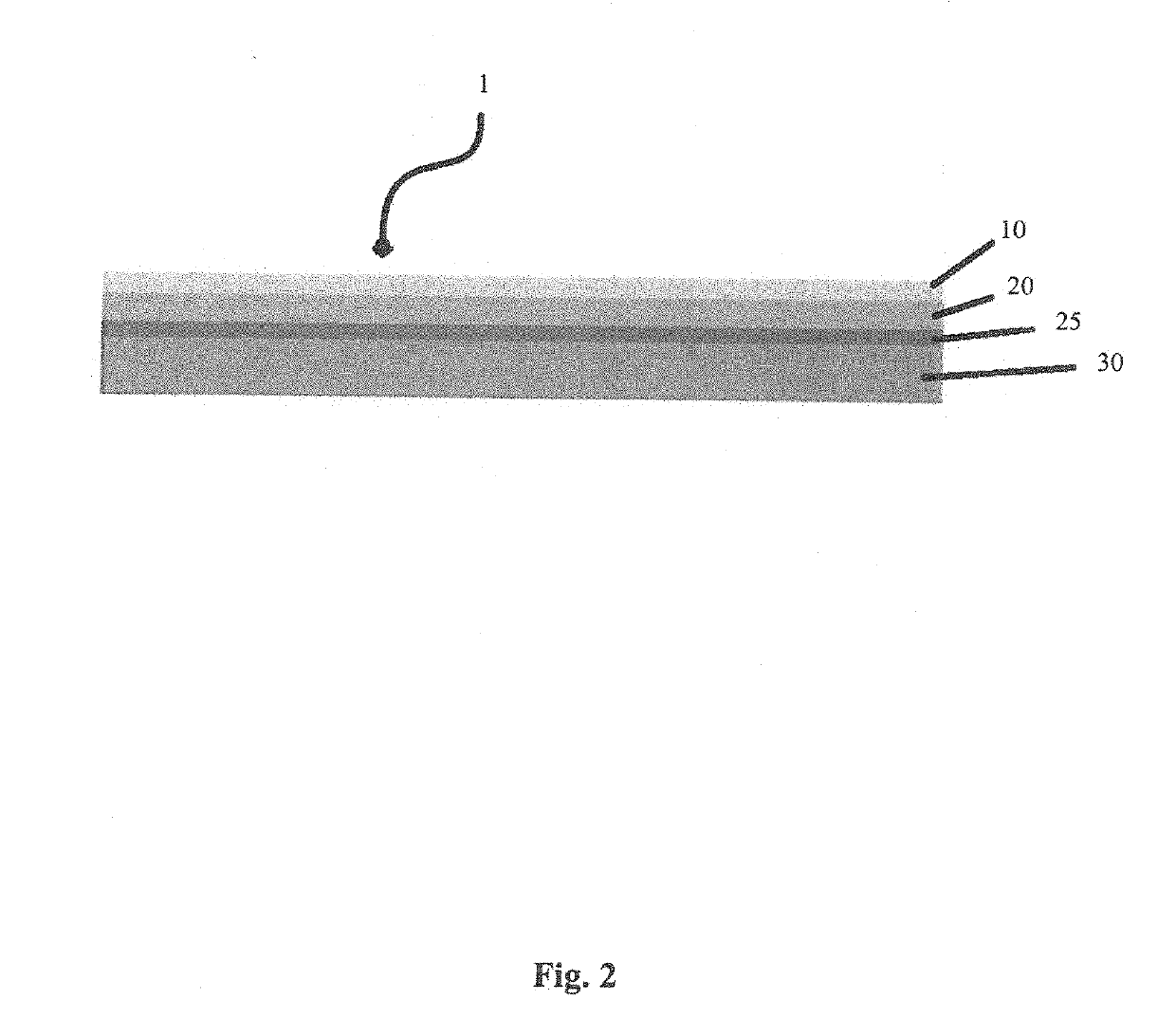
[0034]FIG. 2 shows an embodiment of a vapour barrier lamina 1 comprising a protective layer 10, a moisture-proof foil layer 20, a structural layer 25, and an acoustic insulation layer 30. As shown in FIG. 2, in this embodiment, the acoustic insulation layer 30 is made of mass-loaded plastic and the structural layer 25 is a reinforcing glass fibre scrim.

[0035]The moisture-proof foil layer 20 may be formed from a metal foil, such as aluminium foil and has a permeance in the range between 0.28-5.72 ng·Pa−1·s−1·m−2 (0.005-0.1 Perms (inch-pound)) (ASTM E96). The moisture-proof foil layer 20 may alternatively be formed from polymeric films, such as polyethylene, polyvinyl chloride or acetates, polypropylene, polyester, or silicone coated fabrics.

[0036]The mass-loaded vinyl (MLV) may be made using polyvinyl chloride (PVC), polyethylene, polypropylene and / or ethylene vinyl acetate. The mass-loaded plastic may be loaded with an inert mineral filler such as calcium carbonate, barium sulphate ...


PUM

PropertyMeasurementUnit
Temperatureaaaaaaaaaa
Massaaaaaaaaaa
Electrical resistanceaaaaaaaaaa

Abstract

A vapour barrier lamina, particularly for acoustic insulation of a pipe or duct, including a fiberglass moisture-proof foil layer, an acoustic insulation layer adjacent a first side of the moisture-proof layer, and a protection layer adjacent a second side of the moisture-proof layer. The vapour barrier lamina may also include a structural layer located between the moisture-proof foil layer and the acoustic insulation layer, for additional protection, and the structural layer may be a fiberglass screen.

Description

FIELD[0001]The present invention relates to a vapour barrier lamina, in particular to a vapour barrier lamina for acoustic insulation of a pipe or duct.BACKGROUND[0002]The increasing worldwide demand for cleaner energy sources has led to a sharp increase in the production, processing, transport and consumption of Liquefied Natural Gas (LNG). The industrial facilities handling LNG require extensive industrial insulation to avoid problems such as boil-off, ice build-up and associated fire hazards. It is not uncommon for a cryogenic pipe to operate at a temperature of −168° C. (−334° F.) in ambient conditions of 32° C. (90° F.), requiring extensive insulation.[0003]However, the temperature gradient also creates a considerable natural moisture drive towards the cryogenic pipe. Moisture intrusion into the insulation layers degrades insulation performance, while causing ice build-up. Additionally, moisture intrusion can cause corrosion of the cryogenic pipe under the insulation layer, whi...

Claims


Application Information

Patent Timeline
IPC IPC(8): F16L55/033F16L59/14F16L59/02
CPCB32B2262/101B32B2597/00B32B2307/102B32B2307/3065B32B2307/7246B32B2307/72B32B15/14F16L55/0336F16L59/145F16L59/029B32B27/12B32B27/30B32B15/20F16L57/04F16L58/08F16L58/16B32B5/028B32B5/18B32B5/26B32B27/20B32B27/304B32B27/306B32B27/32B32B27/36B32B2250/04B32B2255/02B32B2255/20B32B2264/104B32B2266/057B32B2307/304B32B2307/5825B32B2307/734B32B2571/00
Inventor TSITOS, GEORGE
Owner PYROTEK PTY LTD
Learn More