Nitride-based light-emitting device
a light-emitting device and nitride-based technology, applied in semiconductor devices, light-emitting devices, semiconductor lasers, etc., can solve problems such as insufficientness, and achieve the effects of reducing operating voltage, reducing waveguide loss, and suppressing leakage curren
- Summary
- Abstract
- Description
- Claims
- Application Information
AI Technical Summary
Benefits of technology
Problems solved by technology
Method used
Image
Examples
embodiment 1
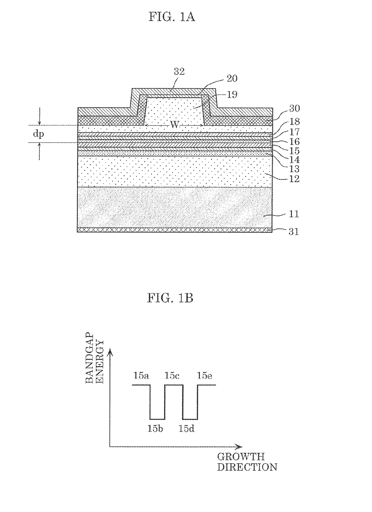
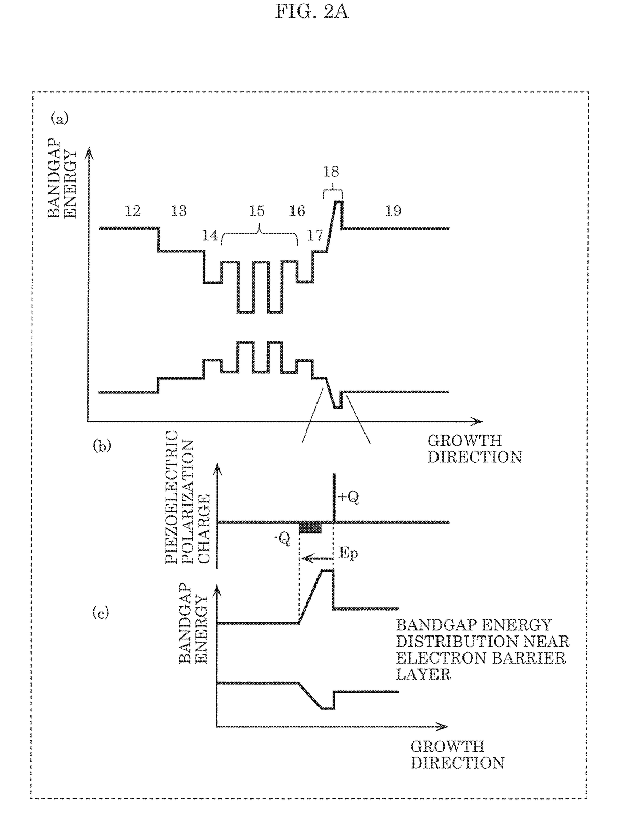
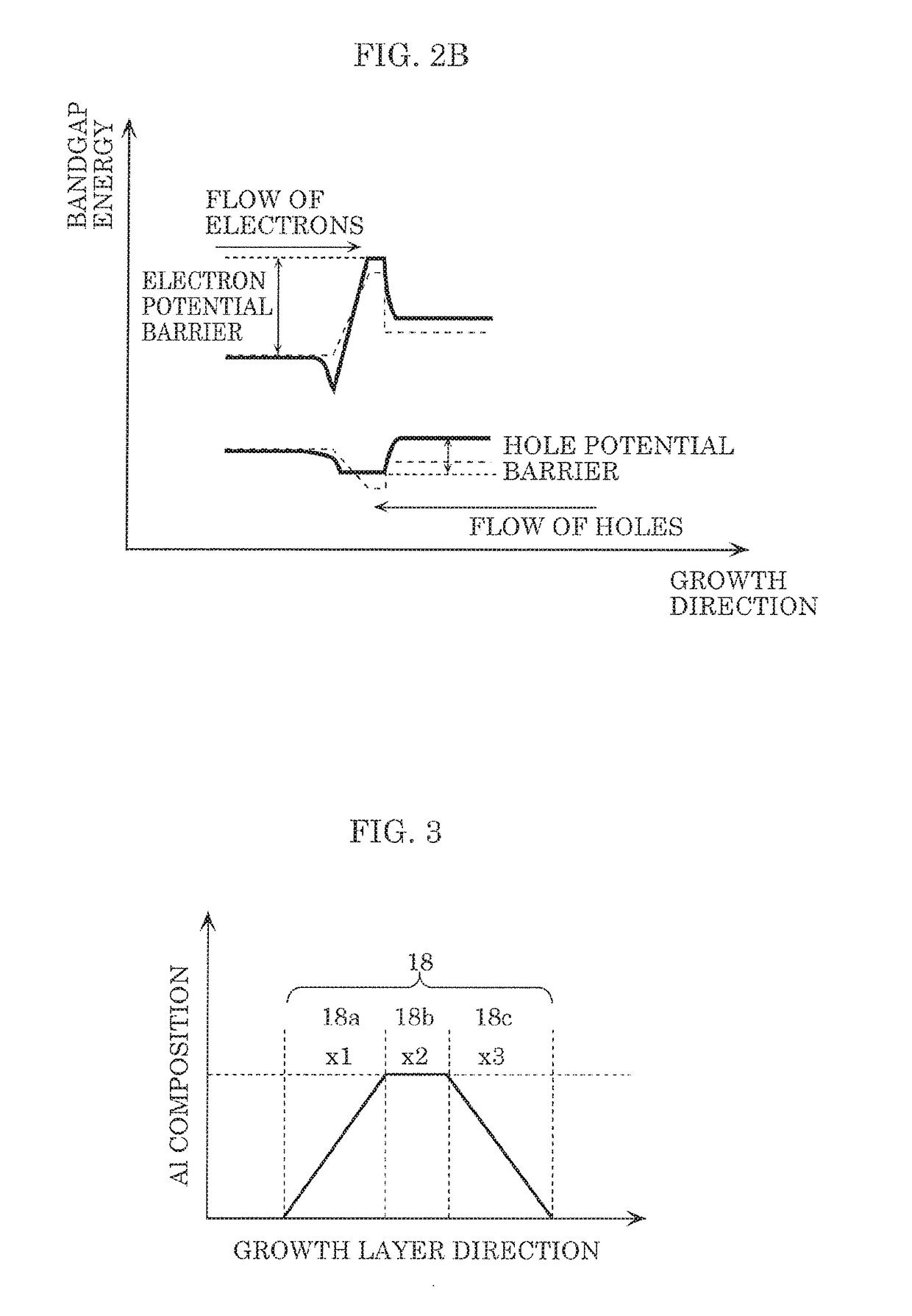
[0065]FIG. 1A illustrates the sectional structure of a nitride-based light-emitting device (hereafter also simply referred to as “light-emitting device”) according to Embodiment 1. FIG. 1A is a sectional view of a light-emitting device including GaN substrate 11, and, on GaN substrate 11: N-type AlGaN cladding layer 12 (film thickness: 1.2 μm); second light guide layer 13 (100 nm) made of N-type GaN; third light guide layer 14 (film thickness: 185 nm) made of undoped InGaN; undoped multiquantum well active layer 15; first light guide layer 16 (film thickness: 100 nm) made of undoped InGaN; intermediate layer 17 (film thickness: 5 nm) made of P-type GaN; P-type electron barrier layer 18; P-type AlGaN cladding layer 19 (film thickness: 660 nm); P-type GaN contact layer 20 (film thickness: 0.1 μm); current block layer 30 transparent to a light distribution; N-type electrode 31; and P-type electrode 32. The width (W) of the ridge is 16.0 μm.
[0066]The distance between the ridge upper por...
embodiment 2
[0170]A light-emitting device according to Embodiment 2 is described below.
[0171]In the light-emitting device according to the foregoing Embodiment 1, the Al composition distribution of electron barrier layer 18 and the Mg doping profile of P-type AlGaN cladding layer 19 and electron barrier layer 18 are designed in detail to achieve all of low voltage, low waveguide loss, and ΔE increase. In the structure of the light-emitting device according to Embodiment 2 of the present disclosure, the doping profile of N-type layers including N-type AlGaN cladding layer 12, second light guide layer 13, and third light guide layer 14 is also adjusted to achieve further loss reduction and voltage reduction. The light-emitting device according to this embodiment is described below.
[0172]An N-type impurity doping profile is described first. In the structure of the light-emitting device according to Embodiment 1, N-type AlGaN cladding layer 12 and second light guide layer 13 are doped with Si of 1×...
embodiment 3
[0193]A light-emitting device according to Embodiment 3 is described below.
[0194]In the structure illustrated in FIG. 15 in Embodiment 2, by setting N1 and N2 to 2×1018 cm−3 or more and 2.5×1018 cm−3 or less and setting high-concentration impurity regions 12a and 13a to be ±5 nm (region width: 10 nm) or more and ±10 nm (region width: 20 nm) or less from the interface between N-type AlGaN cladding layer 12 and second light guide layer 13, a waveguide loss reduction of 0.2 cm−1 or more can be achieved while maintaining the same operating voltage as in the case where N-type AlGaN cladding layer 12 and second light guide layer 13 are uniformly doped with Si of 1×1018 cm−3.
[0195]In Embodiment 3 of the present disclosure, the structure in Embodiment 2 is modified so that N1 and N2 are 2×1018 cm−3 and high-concentration impurity regions 12a and 13a are in a range of ±5 nm (region width: 10 nm) from the interface between N-type AlGaN cladding layer 12 and second light guide layer 13. In thi...
PUM
 Abstract
Description
Claims
Application Information
 - R&D
- Intellectual Property
- Life Sciences
- Materials
- Tech Scout
- Unparalleled Data Quality
- Higher Quality Content
- 60% Fewer Hallucinations
Browse by: Latest US Patents, China's latest patents, Technical Efficacy Thesaurus, Application Domain, Technology Topic, Popular Technical Reports.
© 2025 PatSnap. All rights reserved.Legal|Privacy policy|Modern Slavery Act Transparency Statement|Sitemap|About US| Contact US: help@patsnap.com


