
Organic electroluminescent compound and organic electroluminescent device comprising the same

a technology of organic electroluminescent devices and electroluminescent compounds, which is applied in the direction of luminescent compositions, organic chemistry, chemistry apparatuses and processes, etc., can solve the problems of reducing affecting the luminous efficiency of current fluorescent light-emitting materials, and affecting the luminous efficiency of current fluorescent materials. , to achieve the effect of improving the luminous efficiency, improving the interface characteristics, and increasing the driving voltag

Active Publication Date: 2019-02-28
DOW GLOBAL TECH LLC +1
View PDF3 Cites 3 Cited by
  • Summary
  • Abstract
  • Description
  • Claims
  • Application Information

AI Technical Summary

Benefits of technology

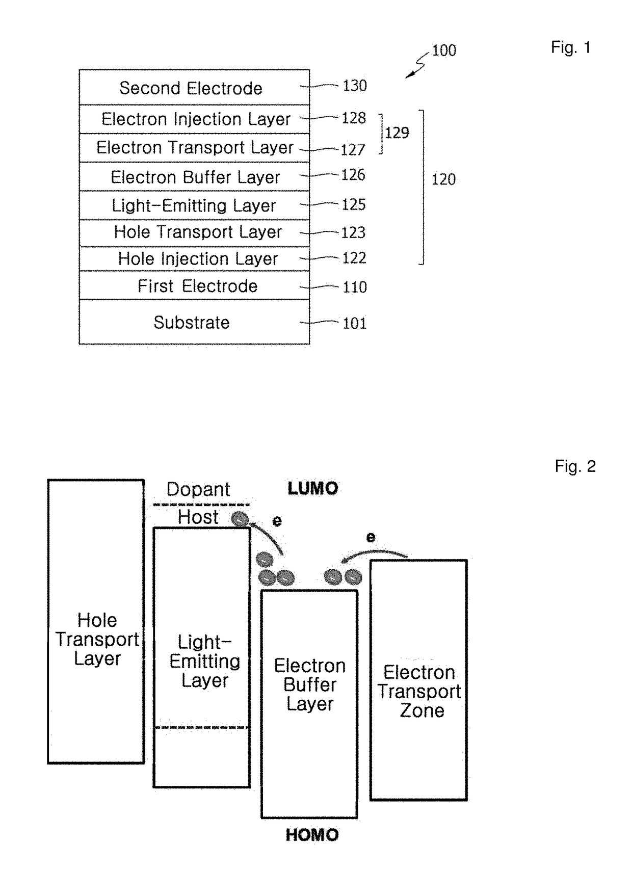
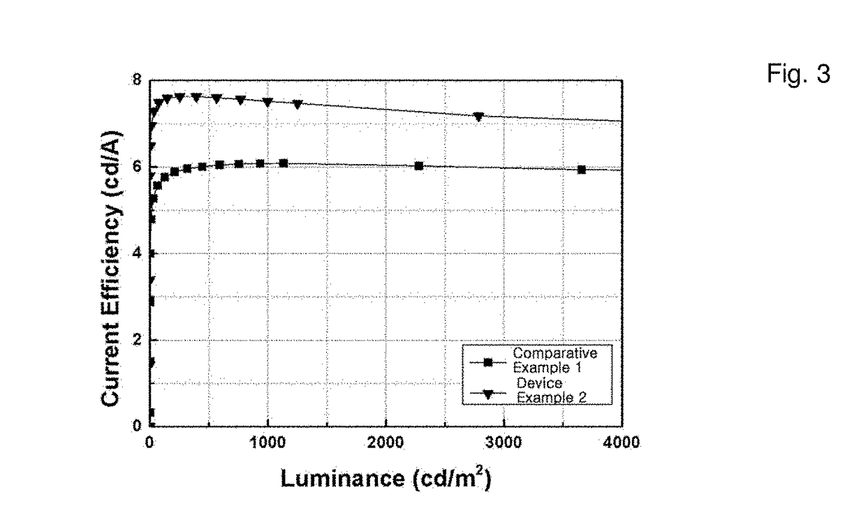
The present invention relates to an organic EL device having a electron buffer layer between the light-emitting layer and electron injection layer. This electron buffer layer controls injection of electrons and improves the interface between these layers, resulting in a device with improved efficiency and lifespan. The device can produce light with high purity color using low driving voltage and has excellent current and power efficiency.

Problems solved by technology

However, in the case of blue light-emitting organic EL devices, excessively formed excitons were dissipated to decrease roll-off at a high current thereby declining characteristics of devices, lifespan of blue phosphorescent materials themselves has a problem with long-term stability, and a sharp decline of color purity occurred over time, and thus were the obstacles to serve a full color display.
Currently used fluorescent light-emitting materials also have various problems.
The first problem is that if the materials are exposed at high temperature in the process of panel production, current property of the devices changes, and thus light-emitting luminance may be accordingly changed.
Also, fluorescent light-emitting materials have lower efficiency characteristics than phosphorescent light-emitting materials.
The light-emitting at an interface has problems with decrease of lifespan of the devices and unsatisfactory efficiency.
The above problems of fluorescent light-emitting materials are difficult to solve by mere improvement of materials themselves.
However, the literature does not recite an organic EL device using the compounds comprising an oxazole or thiazole skeleton in an electron buffer layer.
However, materials of an electron buffer layer are limited to Alq3 derivatives, restriction of electrons is the purpose, and types of materials are not various, and thus analysis for effective luminous efficiency and lifespan improvement is limited.
Thus, the literature has limitation in optimizing devices comprising an electron buffer layer in view of control of electron current property by using pure characteristics of related compounds.

Method used


Image

  • Organic electroluminescent compound and organic electroluminescent device comprising the same
  • Organic electroluminescent compound and organic electroluminescent device comprising the same
  • Organic electroluminescent compound and organic electroluminescent device comprising the same

Examples


example 1

on of Compound B-7

[0053]

Preparation of Compound 1-1

[0054]Acetonitrile (60.0 mL) was added to a mixture of tetrachloropyridine (2.17 g, 10.0 mmol, 217.0 g / mol), phenylboronic acid (2.56 g, 21.0 mmol, 122.0 g / mol), K2CO3 (2.76 g, 20.0 mmol, 138.0 g / mol, 2M in deionized water), and tetrakis(triphenylphosphine)palladium(0) (Pd(PPh3)4) (58.0 mg, 0.05 mmol, 1155.0 g / mol) in a two-neck flask under N2 atmosphere, and then the mixture was stirred under reflux for 4 hrs. The reaction results were monitored by using Thin-layer chromatography (TLC). After cooling the mixture to room temperature, white crystals were precipitated from the solution. The crystals were filtered and directly used in a next step.

[0055]1H NMR (400 MHz, CDCl3, ppm): 7.94 (s, 1H), 7.79-7.80 (d, J=6.8 Hz, 4H), 7.42-7.48 (m, 6H). LC-MS-ESI (m / z): C17H11Cl2N calculated 299.03, found (M+H)+ 300.0349.

Preparation of Compound B-7

[0056]Dioxane (150.0 mL) was added to a mixture of compound 1-1 (3.00 g, 10.0 mmol, 300.0 g / mol), co...

example 2

on of Compound B-24

[0058]

Preparation of Compound 2-1

[0059]Acetonitrile (60.0 mL) was added to a mixture of tetrachloropyridine (2.17 g, 10.0 mmol, 217.0 g / mol), naphthalene-2-yl-boronic acid (3.61 g, 21.0 mmol, 172.0 g / mol), K2CO3 (8.70 g, 63.0 mmol, 138.0 g / mol, 2M in deionized water), and Pd(PPh3)4 (58.0 mg, 0.05 mmol, 1155.0 g / mol) in a 250 mL two-neck flask under N2 atmosphere, and then the mixture was stirred under reflux for 4 hrs. The reaction results were monitored by using TLC. After cooling the mixture to room temperature, a lot of white powder was precipitated from the solution. The powder was filtered and recrystallized in alcohol to obtain white powder as a final product.

[0060]1H NMR (400 MHz, CDCl3, ppm): 8.33 (s, 2H), 8.02 (s, 1H), 7.88-7.94 (m, 8H), 7.50-7.56 (m, 4H). LC-MS-ESI (m / z): C25H15Cl2N calculated 399.06, found (M+H)+ 400.0654.

Preparation of Compound B-24

[0061]Dioxane (150.0 mL) was added to a mixture of compound 2-1 (4.00 g, 10.0 mmol, 400.0 g / mol), compoun...

example 3

on of Compound B-56

1-Phenyl-2-(4-(4,4,5,5-tetramethyl-1,3,2-dioxaborolan-2-yl)phenyl)-1H-benz[d]imidazole

[0063]

[0064]A 500 mL four-neck round-bottomed flask (RBF) equipped with an overhead stirrer, a nitrogen inlet, a 125 mL addition funnel, and a thermocouple was purged with anhydrous nitrogen for 10 min. The flask was charged with 2-(4-bromophenyl)-1-phenyl-1H-benzo[d]imidazole (25.0 g, 71.59 mmol) and THF (250.0 mL), and then cooled to −71° C. of internal temperature. 1.6 M n-butyl lithium solution (67.0 mL, 107.2 mmol) in hexane was added dropwise into the flask via an addition funnel for 30 min, and the mixture was further stirred at an internal temperature of −72° C. of for 30 min. 2-isopropoxy-4,4,5,5-tetramethyl-1,3,2-dioxaborolane (32.0 mL, 171.99 mmol) was added to the resulting dark red solution via an addition funnel for 30 min while maintaining the temperature of below −70° C. After removing a cooling bath, the brown slurry was warmed to room temperature and stirred for...


PUM


Abstract

The present invention relates to an organic EL device comprising an electron buffer material, and a first electrode, a second electrode opposing the first electrode, a light-emitting layer disposed between the two electrodes, and an electron transport zone and an electron buffer layer disposed between the light-emitting layer and the second electrode. By using an electron buffer material according to the present invention, the organic EL device having low driving voltage, high luminous efficiency, and excellent lifespan can be provided.

Description

TECHNICAL FIELD[0001]The present invention relates to an organic electroluminescent compound and an organic electroluminescent device comprising the same.BACKGROUND ART[0002]A low molecular green light-emitting organic electroluminescent (EL) device was developed by Tang, etc., of Eastman Kodak in 1987 by using TPD / ALq3 bi-layer consisting of a light-emitting layer and an electron transport layer. Thereafter, the development of organic EL devices was rapidly effected and the devices were currently commercialized. Current organic EL devices mostly use phosphorescent materials with excellent luminous efficiency for panel manufacture. In the case of red and green light-emitting organic EL devices, commercialization of organic EL devices by using phosphorescent materials was succeeded. However, in the case of blue light-emitting organic EL devices, excessively formed excitons were dissipated to decrease roll-off at a high current thereby declining characteristics of devices, lifespan of...

Claims


Application Information

Patent Timeline
Patent Type & Authority Applications(United States)
IPC IPC(8): H01L51/00H01L51/50H10K99/00
CPCH01L51/0067H01L51/0072H01L51/5096H01L51/5012H01L51/508H01L51/5004H01L51/5056H01L51/5092C07D417/14C07D413/14C07D401/14C07D417/10C07D413/10C07D403/10C07D495/04C07D491/048C07D413/04C09K11/06C09K2211/1011C09K2211/1029C09K2211/1033C09K2211/1037C09K2211/1044C09K2211/1059C09K2211/1088C09K2211/1092H10K85/626H10K85/615H10K85/654H10K85/6576H10K85/6574H10K85/657H10K85/6572H10K50/18H10K50/166H10K50/11H10K50/15H10K50/171H10K2101/40
Inventor CHO, SANG HENA, HONG YEOPTANG, ZHENGMINGFENG, SHAOGUANGMOON, DOO-HYEON
Owner DOW GLOBAL TECH LLC
Learn More