
Thin film transistor, method of producing the same, liquid crystal display, and thin film forming apparatus

a thin film transistor and insulating film technology, applied in the direction of transistors, optics, instruments, etc., can solve the problems of display failure, tft operation failure, and material which has been used for gate insulating films in the past are not satisfactory from the points of both dielectric withstand voltage and carrier, so as to improve the withstand voltage, improve the interface characteristic, and improve the effect of withstand voltag

Inactive Publication Date: 2005-04-12
LG DISPLAY CO LTD
View PDF4 Cites 4 Cited by
  • Summary
  • Abstract
  • Description
  • Claims
  • Application Information

AI Technical Summary

Benefits of technology

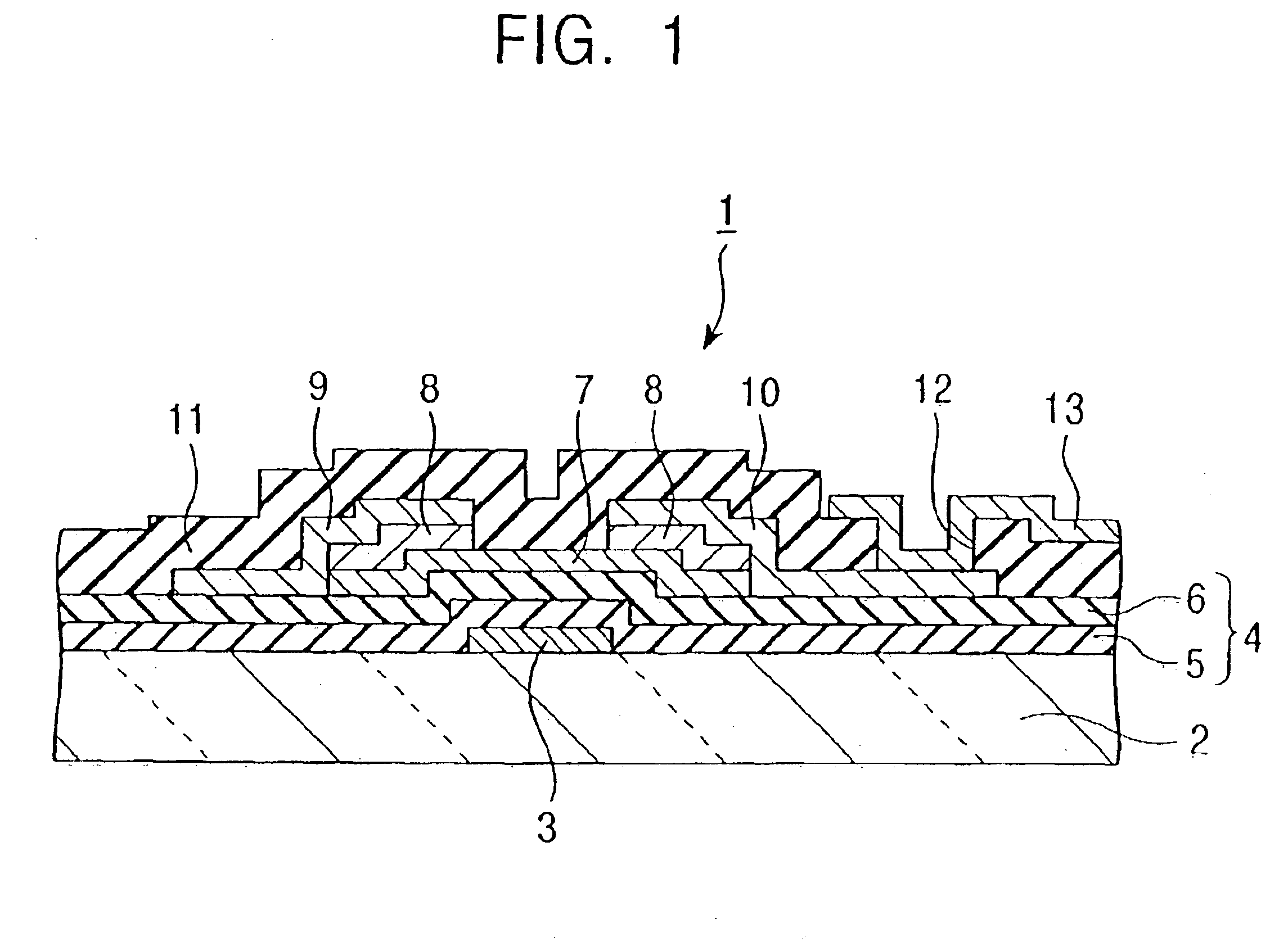
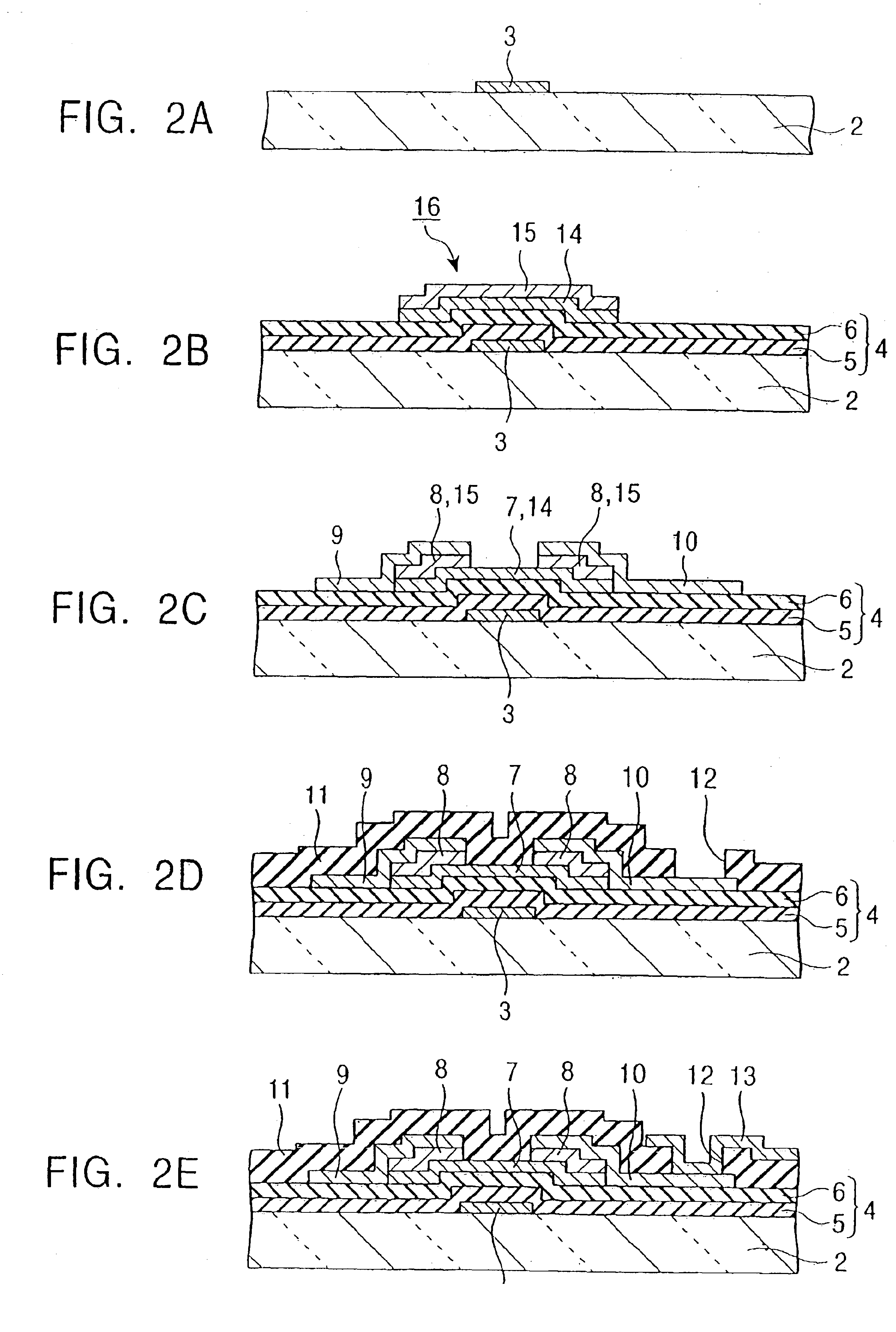
To achieve the above object, in the TFT of the present invention, a gate electrode and a semiconductor active film are formed on a substrate with a gate insulating film, which is formed of two layered insulating films, located therebetween, the gate insulating film being made up of a first gate insulating film which is disposed on the same side as the gate electrode and improves a withstand voltage between the gate electrode and the semiconductor active film, and a second gate insulating film which is disposed on the same side as the semiconductor active film and improves an interface characteristic between the gate insulating film and the semiconductor active film.
In other words, the TFT of the present invention intends to realize a gate insulating film which has in itself a desired dielectric withstand voltage and renders the semiconductor active film to have a desired carrier mobility, by forming the gate insulating film with two layered insulating films made of such materials as functioning respectively to improve the withstand voltage between the gate electrode and the semiconductor active film, and to improve the interface characteristic between the gate insulating film and the semiconductor active film. The phrase “improve the interface characteristic between the gate insulating film and the semiconductor active film” used herein means that the carrier mobility in the semiconductor active film is improved as a result of forming the second gate insulating film.
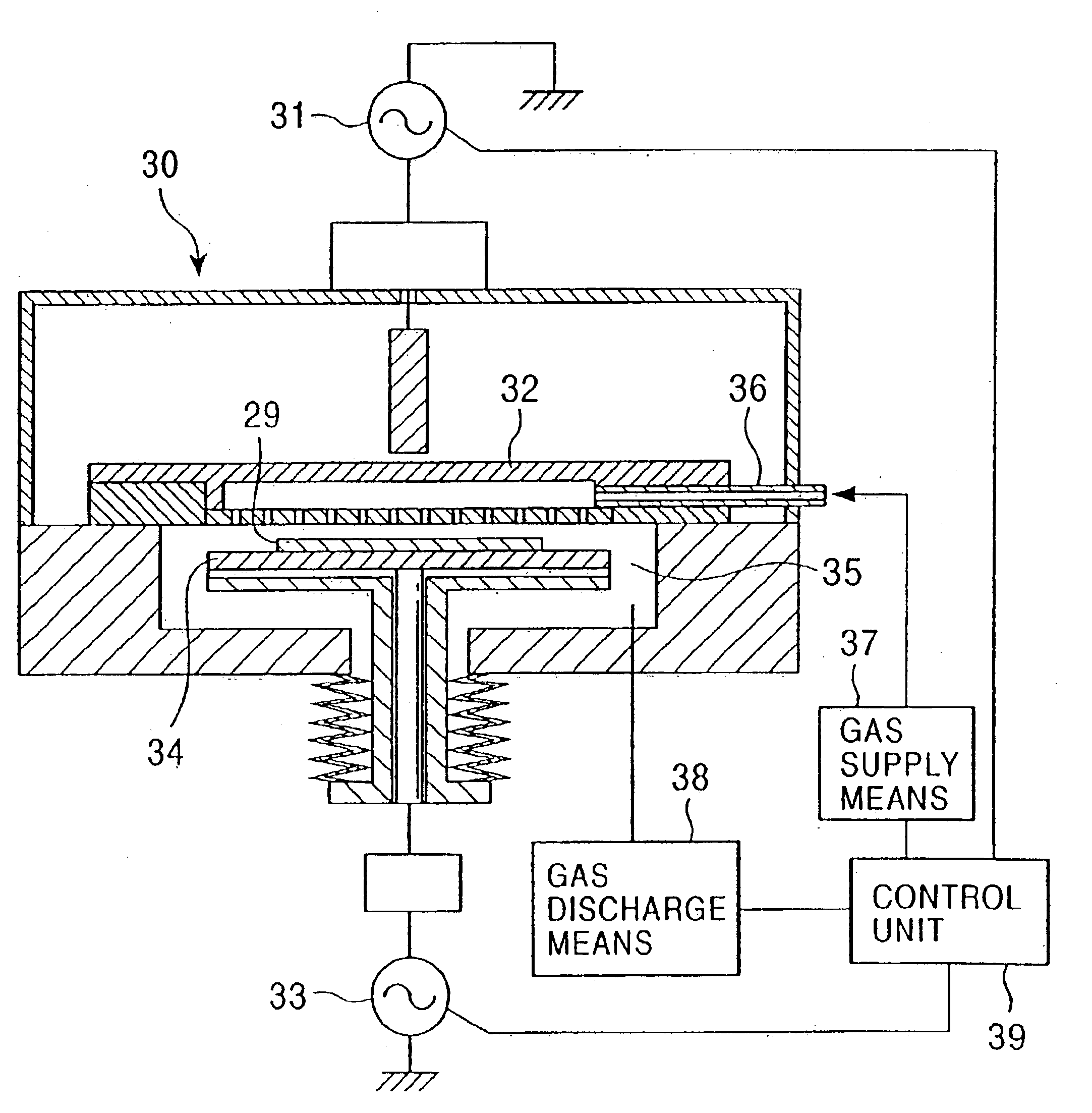
With any of the above methods, the two layered gate insulating films having different characteristics can be formed successively and easily just by forming both the first and second gate insulating films of silicon nitride films, and changing over the radio-frequency power or the composition of the gas mixture at the time of shift from the first gate insulating film forming step to the second gate insulating film forming step. As a result, the step of forming the gate insulating film is not so complicated as the example of the two-layered structure of Ta2O5 and Si3N4 mentioned above in connection with the related art, and a TFT array board can be manufactured with productivity at a level not so lower than the case of forming a one-layer gate insulating film.
The liquid crystal display of the present invention employs a TFT array board having the TFT's which provide a high dielectric withstand voltage between the gate electrode and the semiconductor active film, and ensure a great carrier mobility in the semiconductor active film. Therefore, a liquid crystal display can be realized which has a high response speed and is superior in yield and reliability.

Problems solved by technology

Also, the gate insulating film is a factor responsible for the occurrence of surface defects.
The dielectric withstand voltage is a problem inherently depending on the gate insulating film itself, whereas the carrier mobility in the semiconductor active film is affected by an interface characteristic between the gate insulating film and the semiconductor active film.
The term “dielectric withstand voltage” means a maximum voltage until which the gate insulating film is endurable against dielectric breakdown in a test wherein the voltage applied between the gate electrode and the semiconductor active film is increased gradually if the dielectric withstand voltage is lower than a desired design value, the gate insulating film would be liable to break down, thus resulting in an operation failure of the TFT and hence a display failure.
Although the dielectric withstand voltage and the carrier mobility are, as described above, important factors in achieving TFTs with good electrical characteristics and high reliability, the materials which have been usually employed for the gate insulating film in the past are not satisfactory from points of both the dielectric withstand voltage and the carrier mobility.
Also, although it has been hitherto proposed to combine two kinds of layers for giving the gate insulating film desired capabilities like the above-mentioned example of the two-layered structure of Ta2O5 and Si3N4, this method has such problems that the step of forming the gate insulating film is complicated and the productivity of TFT array boards is deteriorated.

Method used


Image

  • Thin film transistor, method of producing the same, liquid crystal display, and thin film forming apparatus
  • Thin film transistor, method of producing the same, liquid crystal display, and thin film forming apparatus
  • Thin film transistor, method of producing the same, liquid crystal display, and thin film forming apparatus

Examples


examples

The correlation between the optical band gap of the gate insulating film and various characteristics in the TFT of the present invention was studied. Results of the studies are reported below.

First, how the optical band gap varies depending on values of the applied RF power in forming the gate insulating film was studied. Using the two-frequency excitation plasma CVD apparatus, SiNx films were formed while the RF excitation power (Rf1) of 40.68 MHz was changed to four values, i.e., 200, 400, 600 and 800 arb. (arb. represents an arbitrary unit) and the substrate bias power (Rf2) of 13.56 MHz was changed from 0 arb. to 400 arb. for each value of the RF excitation power. The optical band gap of each of the formed SiNx films was measured. As other conditions for the film formation, the flow rate ratio of material gases was set to SiH4 / NH3 / N2:40 sccm / 160 sccm / 600 sccm, the substrate temperature was set to 300° C., and the pressure within the chamber was set to 250 Pa. Measured results ar...


PUM

PropertyMeasurementUnit
optical band gapaaaaaaaaaa
bias poweraaaaaaaaaa

Abstract

The invention intends to provide a TFT having a gate insulating film which has a high dielectric withstand voltage and can ensure a desired carrier mobility in an adjacent semiconductor active film. A gate electrode and a semiconductor active film are formed on a transparent substrate with a gate insulating film, which is formed of two layered insulating films, held between them. The gate insulating film is made up of a first gate insulating film which improves a withstand voltage between the gate electrode and the semiconductor active film, and a second gate insulating film which improves an interface characteristic between the gate insulating film and the semiconductor active film. The first and second gate insulating films are each formed of a SiNx film. The optical band gap of the first gate insulating film has a value in the range of 3.0 to 4.5 eV, and the optical band gap of the second gate insulating film has a value in the range of 5.0 to 5.3 eV.

Description

BACKGROUND OF THE INVENTION1. Field of the InventionThe present invention relates to a thin film transistor, a method of producing the thin film transistor, a liquid crystal display, and a thin film forming apparatus. More particularly, the present invention relates to the structure of a gate insulating film in a thin film transistor of the reverse stagger type.2. Description of the Related ArtFIG. 14 concerns with a conventional ordinary liquid crystal display using thin film transistors (hereinafter referred to as TFTs), and illustrates one example of the structure of a TFT array board including TFTs of the reverse stagger type, gate lines, source lines, etc. In such a TFT array board, as shown in FIG. 14, gate lines 50 and source lines 51 are arranged on a transparent substrate in a matrix pattern. Each of areas surrounded by the gate lines 50 and the source lines 51 serves as one pixel 52, and a TFT 53 is provided for each pixel 52. FIG. 15 is a sectional view showing a construc...

Claims


Application Information

Patent Timeline
Patent Type & Authority Patents(United States)
IPC IPC(8): H01L29/40H01L29/49H01L21/316G02F1/136G02F1/1368H01L21/318H01L21/336H01L29/786
CPCH01L29/4908H01L29/786
Inventor SUNG, CHAE GEE
Owner LG DISPLAY CO LTD
Learn More