
Interface circuit for a capacitive accelerometer sensor

a capacitive accelerometer and interface circuit technology, applied in logic circuit interface arrangements, logic circuit coupling/interface arrangements, instruments, etc., can solve the problems of difficult to manage the parasitic capacitance of switches used to implement programmability, difficult to implement feedback capacitors, and difficult to make such a small capacitor programmable and have a fine grain size of programmability, etc., to achieve the effect of relatively easy precise gain trimming

Active Publication Date: 2018-12-20
EM MICROELECTRONIC-MARIN
View PDF0 Cites 3 Cited by
  • Summary
  • Abstract
  • Description
  • Claims
  • Application Information

AI Technical Summary

Benefits of technology

The proposed solution in this patent makes it easier to trim the gain and select the range of the device because it divides the programmable burden into different capacitors instead of using one single capacitor for both tasks. Specifically, a grounded capacitor is used for fine size gain trimming, which makes it easier to achieve precise gain trimming. Two floating programmable capacitors are used for acceleration range selection tuning with a coarse grain size, which improves the efficiency of tuning.

Problems solved by technology

It is difficult to make such a small capacitor programmable and to have a fine grain size of programmability, for example, 1% of 80 fF.
Since the feedback capacitor Cf is a floating capacitor, it is hard to manage the impact of the parasitic capacitance of switches used to implement the programmability.
It is very challenging to implement the feedback capacitor Cf to fulfil both programmability requirements for the grain size and range trimming simultaneously.
It is not provided to implement the feedback capacitor to fulfil both programmability requirements for the grain size and range trimming simultaneously, that it is a drawback.
Nothing is provided to implement a feedback capacitor to fulfil both programmability requirements for the grain size and range trimming simultaneously, that it is a drawback.
The patent application US 2015 / 0280668 A1 describes a capacitive programmable gain amplifier, but nothing is provided for tuning easily the grain size and range trimming simultaneously, that it is a drawback.

Method used


Image

  • Interface circuit for a capacitive accelerometer sensor
  • Interface circuit for a capacitive accelerometer sensor
  • Interface circuit for a capacitive accelerometer sensor

Examples


Embodiment Construction

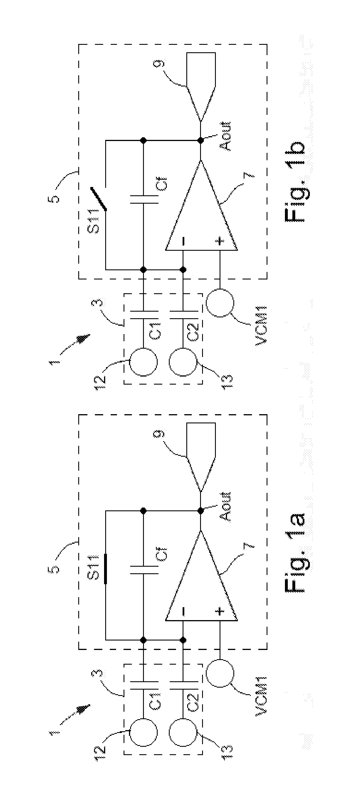
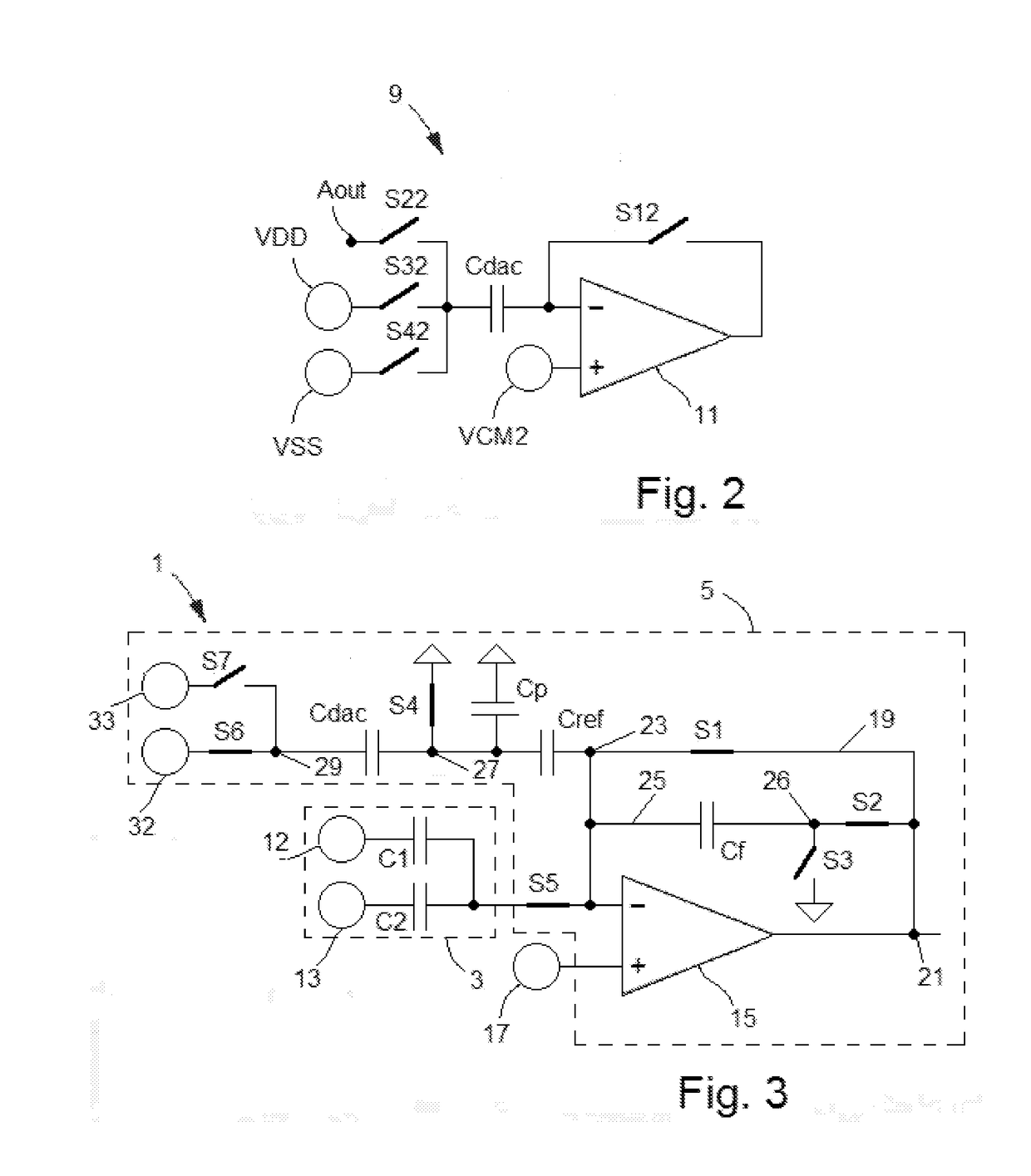
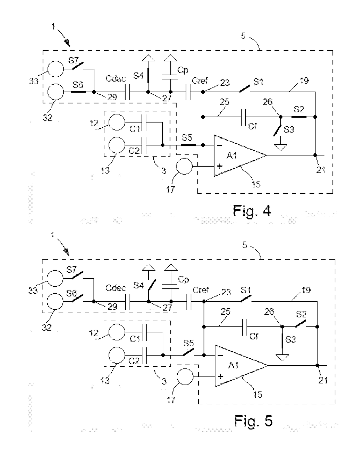
[0033]An embodiment of the present invention will now be described in detail with reference to the attached figures. The invention will be described in the context of a capacitive accelerometer comprising two capacitors. However, the disclosed capacitive accelerometer is not limited to a solution comprising two capacitors. The disclosed accelerometer may operate as a multi-axis accelerometer (e.g. axes x, y and z). Identical or corresponding functional and structural elements which appear in different drawings are assigned the same reference numerals.

[0034]FIG. 3 illustrates a capacitive accelerometer system or device 1, referred to simply as a capacitive accelerometer or accelerometer, according to an example of the present invention. There is shown a micro-electro-mechanical system (MEMS), which operates as a capacitive accelerometer sensor 3. In this example, the sensor 3 comprises a first electrode, a second electrode and a third electrode. In this example, all the electrodes ar...


PUM


Abstract

The present invention relates to an interface circuit for a capacitive accelerometer sensor for measuring an acceleration value sensed by the sensor. The interface circuit comprises a plurality of electrical switches and three programmable capacitors. Two of the programmable capacitors are arranged to implement gain trimming of the interface circuit, while one of the programmable capacitors is arranged to implement acceleration range selection.

Description

[0001]This application claims priority from European patent application No. 17176258.6 filed on Jun. 15, 2017, the entire disclosure of which is hereby incorporated herein by reference.TECHNICAL FIELD[0002]The present invention relates to an interface circuit for a capacitive accelerometer sensor for converting charges received from the capacitive accelerometer sensor into a useful signal for a given application. The invention also relates to a method for operating the interface circuit.BACKGROUND OF THE INVENTION[0003]A capacitive accelerometer is an accelerometer device which measures accelerations (on a surface) using capacitive sensing techniques. It can sense and record acceleration on equipment or devices and converts this acceleration into electrical currents or voltages. Capacitive accelerometers are also sometimes referred to as vibration sensors. They comprise a capacitive micro-electro-mechanical system (MEMS) element operating as a capacitive accelerometer sensor connect...

Claims


Application Information

Patent Timeline
IPC IPC(8): G01P15/125G01D5/24H03G3/00H03F3/00
CPCG01P15/125G01D5/24H03G3/008H03F3/005H03K19/017509G01D5/241G01P15/0802G01H11/06B81B2201/0235
Inventor TAO, YONGHONGGROSJEAN, SYLVAINDAGA, JEAN-MICHEL
Owner EM MICROELECTRONIC-MARIN
Learn More